
Here is my latest build: a vacuum tube FM superheterodyne receiver.
This project was born out of frustration with medium wave (AM) broadcasting: the constant parasitic noise, the lack of stations, and poor content. I decided to take on this challenge despite my doubts, since building circuits for VHF frequencies can be tricky. However, by following a few basic rules and assembling it carefully, I had no issues at all—the receiver worked on the first try.
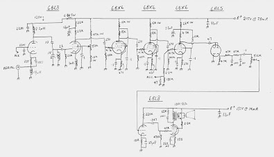
The circuit I used is a pulse counting FM receiver, and you can find the schematic and explanation here:
👉 https://cool386.com/pcrx/pcrx.html
If you read through how it works, you’ll see that it’s a special kind of superheterodyne that doesn’t need any IF transformers, no dual-section variable capacitors, and only requires a single coil to operate. Best of all, it needs no alignment whatsoever.
These amazing features are possible because it uses a very low intermediate frequency, around 150 kHz. This allows the IF amplifier to use resistor-capacitor coupling instead of transformers. Also, thanks to the low IF, a single coil in an autodyne converter can act both as the antenna coil and the oscillator coil, eliminating the need for two separate coils and a dual-gang tuning capacitor.
The detector is a pulse-counting detector. The closer together the pulses are when they enter the detector, the higher the output voltage—and vice versa. In this way, the circuit effectively converts an FM signal into AM, which is then detected by a 6AL5.
The audio output is relatively low—about 100 mV peak-to-peak for strong signals, and 20–50 mVpp for weaker ones. So, a high-gain audio amplifier with high input impedance is required to raise the level to something usable.
In the schematic I used, the ECF80’s triode section is used as a grounded-grid amplifier. Its main purpose is to isolate the local oscillator from antenna-related effects. That grid also receives the AGC (automatic gain control) voltage to prevent overload from strong signals. The pentode section acts as the autodyne converter, generating the IF. The screen grid of the pentode includes a potentiometer to adjust the converter’s sensitivity—this acts as an extra control. Ideally, you tweak this when changing stations, but if you want to skip it, you can preset it using a station in the middle of the band and leave it fixed, sacrificing a bit of sensitivity.
After that come the IF amplifier and detection stages, handled by EF80s. As you’ll see, their circuitry is identical except for the final EF80, which functions as the pulse detector. The first two EF80s amplify the 150 kHz IF to sufficient levels so the final one can perform detection. It also provides the AGC control voltage at its control grid. The IF amplifier has a bandwidth of roughly 300 kHz, set by the coupling capacitors.
The 6AL5 serves as the detector and includes capacitors at its output for FM de-emphasis.
The audio amplifier section shown in the schematic is not what I used—in my case, I used an ECL86 in a classic amplifier circuit from an old record player. Still, the audio signal is so weak that an additional gain stage is required, because the ECL86 alone doesn’t provide enough output to reach full volume.
The build itself is the most delicate part.
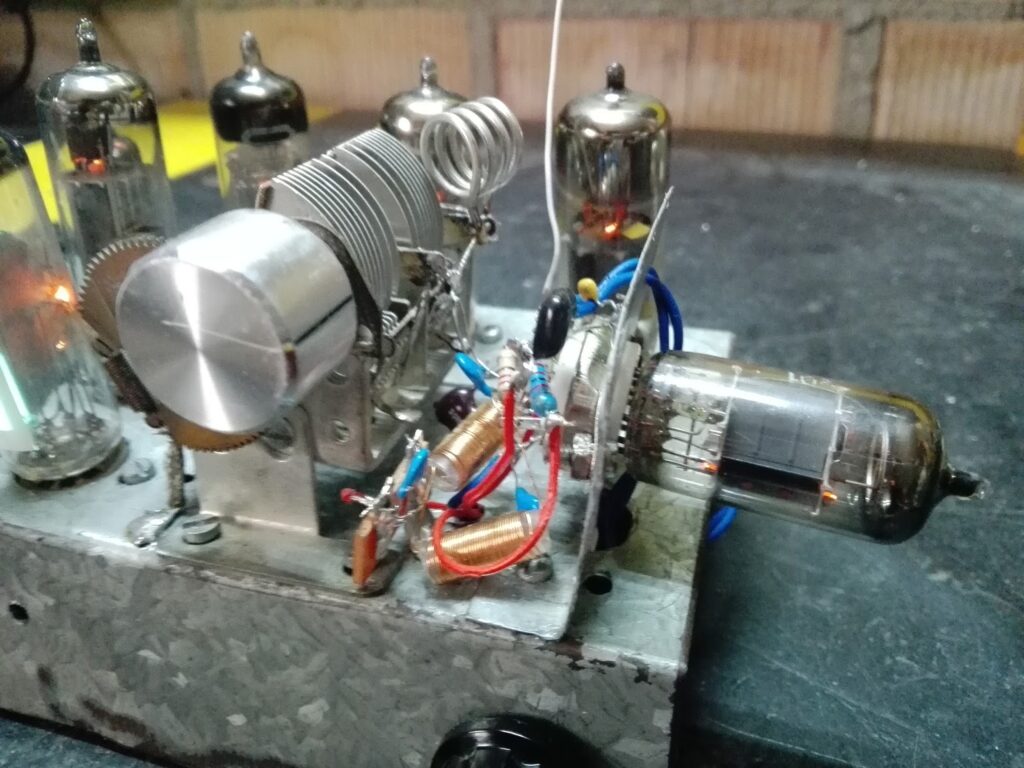
I reused a chassis from a previous project and machined everything needed. I placed the ECF80 on the top side to isolate it from the rest of the circuitry and avoid oscillations or coupling. The FM coil was made from 4 turns of 1 mm silver-plated wire (salvaged from an old telephone cable) wound around a former of about 10 mm diameter.
The RF chokes shown in the schematic can be easily made. Just take about 75 cm of 0.3 mm enameled wire (the diameter isn’t critical, but the length is) and wind it on a small former. I used the plastic tube from an empty Pilot liquid ink pen refill.
In general, all connections should be as short and direct as possible, and the circuit needs a good ground plane. I made all ground connections by soldering directly to the chassis. Heater lines should be bypassed with 100 nF capacitors, especially for the ECF80, and in its case, one end of the heater must be grounded.
After a full day of work, this is how my receiver turned out:
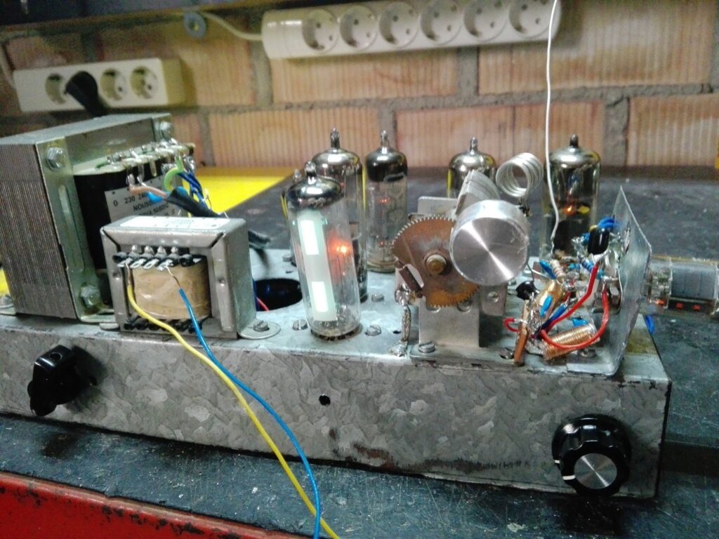
As you can see, I added a magic eye using an EM87 to better visualize station tuning, although the circuit still needs a bit of refinement so that it fully closes on strong stations.
Here’s a short video of the receiver in action:
This receiver has a lot of room for improvement. On my to-do list, I plan to fix the magic eye’s sensitivity, and I’d also like to explore the possibility of receiving FM stereo by modifying the detector circuit to allow for more bandwidth. I’m also considering using voltage regulator tubes to stabilize the receiver’s power supply line, removing the audio amplifier stage and replacing it with a cathode follower output, so the receiver can work as a tuner that can be connected to more powerful and higher-quality audio amplifiers. I’d also like to build the transistorized version, and more…
As you can see, with a bit of patience, this receiver is quite easy to build, and the results are very rewarding. It’s also somewhat ironic that I never managed to get an AM regenerative or superheterodyne receiver to work properly—probably due to poor antennas and being far from the transmitters—and yet this FM receiver worked on the first try, even though FM circuits are theoretically much harder to build. There’s still a lot left to do and improve, but with these results, I already consider it a success. I hope you all enjoyed it.