

After building the previous FM valve receiver, I recently constructed another one based on it—this time deviating a bit from the original design… using P-series television tubes, the kind that nobody usually uses because they’re considered “useless TV tubes.”
I chose to use a “universal” circuit, which carries certain risks, as these circuits have one side of the power line directly connected to the chassis. This means that if the plug is inserted such that the live wire is connected to the metal chassis, and you then touch it, you could receive a deadly 230V shock (or in the case of my home, where I have 230V split-phase, the chassis always sits at around 130V potential regardless of plug orientation—less dangerous, but still potentially lethal).
Naturally, while building and operating it, I use an isolation transformer, which provides galvanic isolation from the mains and eliminates the above dangers, making it safe to touch the chassis.
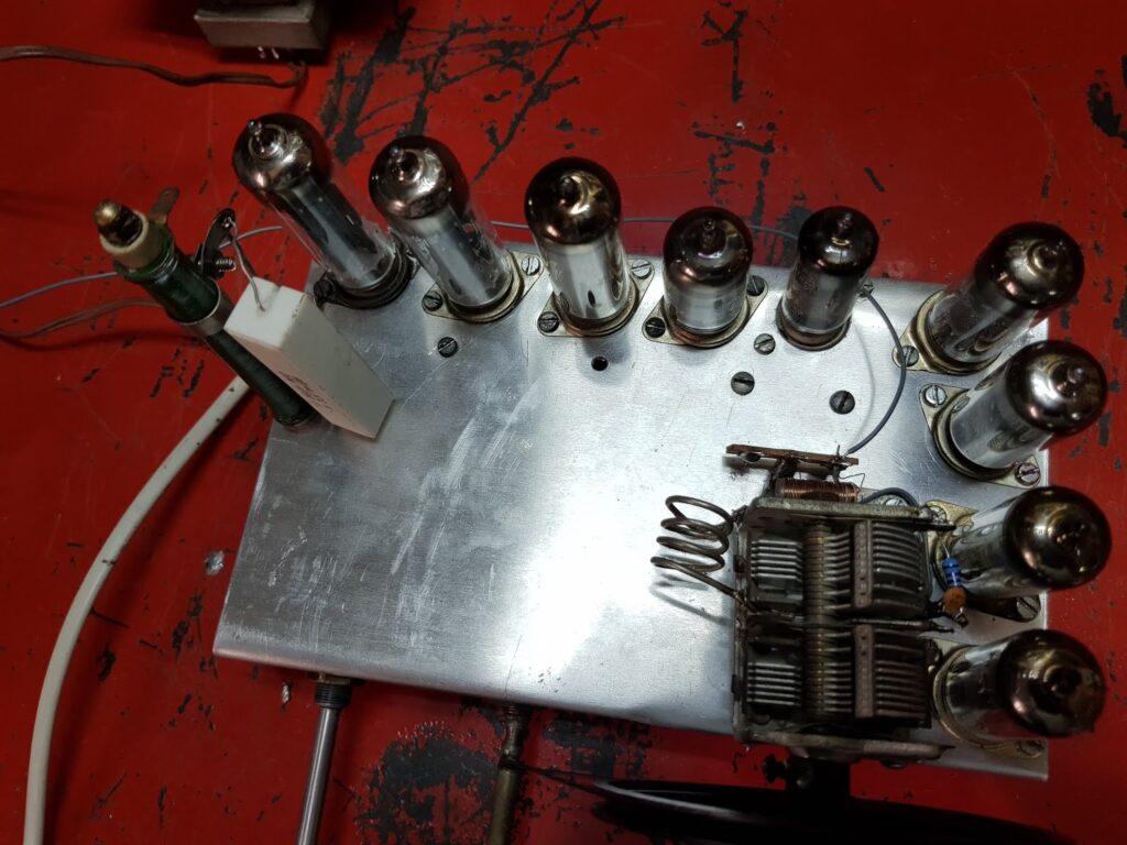
Here are some photos of the new receiver:
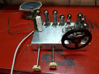
As you can see, there’s one missing control: the screen adjustment for the converter stage. I made a circuit change that eliminates the need for it as a front-panel control—more details on this later.
Tubes used and mechanical assembly
I chose to use:
2x PY82, PL82, ECC82, EB91, 3x EF184, and a PCF80 (which could easily be replaced by a PCF802). The mechanical assembly was homemade from an aluminum sheet on which I marked all the measurements, cutouts, etc. It was relatively easy to machine everything—even bending it by hand, though that part took a bit more effort and may not be perfect. Still, I’m happy with the result. Of course, you could use different valves—for example, a single PY88 as rectifier, or even two, which would increase the filament voltage and reduce the power dissipated in the filament resistor. That’s up to personal preference.
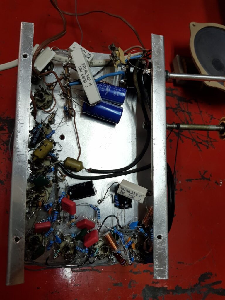
Power supply and audio section
I used two PY82 tubes in parallel, which wasn’t strictly necessary, but I had them on hand. Using both reduces power dissipation in the filament resistor. All filaments are wired in series, totaling about 94V at 0.3A. I used a diode to cut the negative half-cycle, further reducing filament power dissipation. In the end, I only needed a ~230-ohm 15W resistor, which I achieved using two high-power resistors in parallel.
The audio section is simple: a PL82 as power amp and an ECC82 as preamp. There’s no negative feedback, and the 3K output transformer is mounted directly on the speaker (visible in the photo). Obviously, this stage isn’t hi-fi, but it works perfectly—loud enough and sounds quite decent.
Receiver section
It’s the same as in the previous receiver. The only change is that I tweaked the PCF80 stage so that the “oscillation” adjustment of the mixer isn’t as critical. Now, a single trimmer can be set for maximum sensitivity at the center of the FM band and then left alone.
Naturally, sensitivity drops off as you move away from center, but not drastically, and most stations still come in fine.
The modification was to power both the triode plate and the adjustment potentiometer from the same supply point, which stabilizes the screen grid voltage and makes the control less critical.
I also modified the AGC (automatic gain control) line, anticipating the addition of a magic eye indicator. Measuring voltage at the modified AGC line, I found that the strongest signal puts it at around –20V, which is perfect for a EM84 or similar magic eye.
Future improvements
There’s still a lot to explore with these receivers. I’d like to experiment with adding automatic frequency control (AFC) so that stations can be “locked” at peak sensitivity without careful tuning.
Another idea is modifying the detector stage to allow greater bandwidth, enabling an MPX signal to be extracted for stereo FM decoding. In this receiver, I’d also need to shield the PCF80/PCF802, to prevent interference with nearby radios and eliminate detuning when your hand approaches the valve. To reduce radiation and antenna influence on tuning, I’m also considering adding an RF amplifier stage using a PCC84, ECC189, ECC81 or similar tube, though that would add complexity.
I also plan to build a wooden cabinet for this receiver so I can use it daily without carrying the isolation transformer around. In that case, all metal parts will be fully isolated, making it impossible for anyone to receive an electric shock—thus eliminating the need for the isolation transformer altogether.
As for the schematic: since it’s quite similar to the original and I don’t have much time now, I’ve chosen not to post it. But if anyone asks in the comments and I find time, I’d be happy to draw and share it.
Finally, here’s a short video of the receiver in action: