As a summer project, I set out to build a Mullard 5-10 type amplifier using recycled materials I had in my workshop, and thus this amplifier was born.
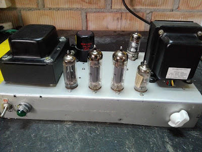
The chassis is an aluminum sheet taken from an old transistor radio kit from the 1970s, which is why you can see various drilled holes along the chassis; these were where the different PCB modules were screwed in. It was easy to work on—I just had to clean it a bit, mark where the holes would go, and with a drill press, hole saws of different diameters, a file, and a lot of patience, I made all the necessary holes. After that came the bending of the sheet metal, which was a bit tricky and didn’t come out perfectly as you can see in the photo… but it’s already quite an achievement considering I did it without a press brake.
Then came the most fun part: assembling the circuit. Although I tried to make a copy, I added a couple of modifications to adapt to what I had in the workshop. You can see the original schematic with detailed circuit description and chassis measurements here. The amplifier, as its name indicates, consists of 5 tubes: EZ80 (or EZ81), EL84, EL84, ECC83, and EF86.
In my case, I used the EZ80 as the rectifier because I had one on hand, and it also has a higher internal resistance, which causes a larger voltage drop when rectifying than diodes do. That was very convenient since the power transformer I had available provides 350-0-350V instead of the 300-0-300V specified in the schematic. Thanks to the EZ80 and increasing the anode resistor value of the diodes, I managed to get about 350V on the first filter capacitor, a bit higher than the 320V expected, but it still works perfectly.
Another modification was replacing the EF86 with an EF40 because I had a rimlock socket and several EF40 tubes, whereas I had no EF86. Circuit-wise, no changes were necessary since the EF40 is identical to the EF86 except for the base type.
I also added an output impedance selector using a switch. Depending on its position (4, 8, or 16 ohms), it changes the parallel resistor-capacitor network in the negative feedback loop and the output tap on the transformer, allowing quick and convenient changes of output impedance to connect different speakers — very handy especially for testing.
Although I built the version without tone controls, I did add a volume control. Also worth mentioning is that the output transformer I’m using is good quality and has a 10kΩ plate-to-plate impedance, somewhat higher than specified in the circuit but it still works well. Of course, the EL84 output stage is configured in ultralinear mode, with 33% taps as the output transformer provides, and using the “normal loading” configuration, i.e., 270-ohm cathode resistors.
The power and sound quality are practically identical to those published by Mullard for the circuit. Besides sounding very good, I’m actually using it as a computer amplifier and I must say it performs perfectly, so I plan to use it a lot.
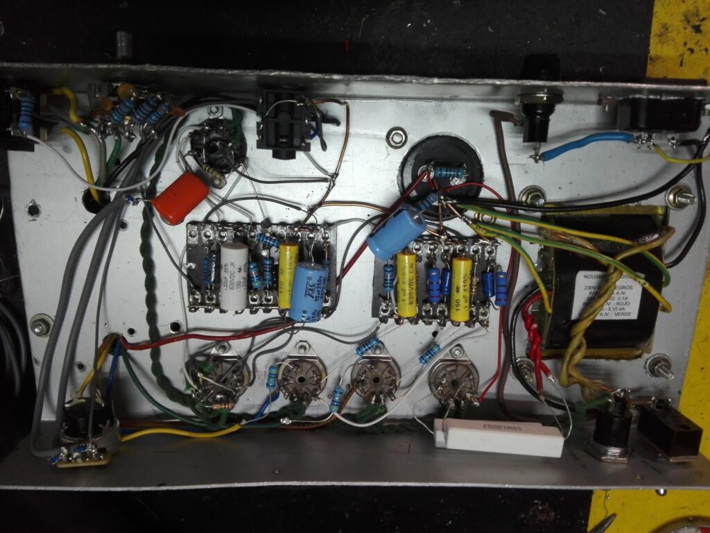
Here are some photos of the amplifier’s interior: