After the successful repair of the Vieta A-225, I’ve come across a slightly older model, the Vieta A-215.
It’s a relatively rare model but very similar in circuitry to the well-known Vieta A-217. The circuit is practically identical, except for the values of the feedback capacitors in the power stage.
Futhermore, another difference between the two amplifiers is their appearance: the Vieta A-217 has a more metallic look, while the A-215 has a more classic beige finish. Personally, I prefer the design of the A-215, so I think it’s a great acquisition.
Although it might be tempting, it’s important to remember not to plug it into the mains to see if it works. In 99% of cases, this will cause more problems, mainly due to faulty capacitors.
It’s time to get to work and restore it to like-new condition!
State of the Amplifier
The first thing to note is that, overall, it’s in decent condition.
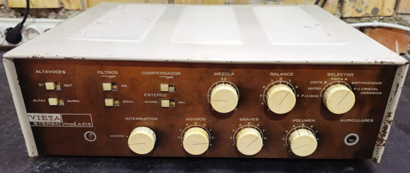
The front panel has some areas where the paint has chipped off, so it will need to be repainted to restore its cosmetic condition.
Looking at the back:
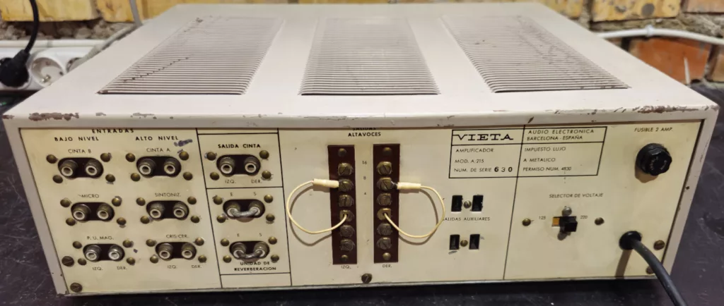
It’s also in fairly good condition. The cover for the voltage selector is missing, but other than that, everything else looks fine.
The reverb unit bridges are also in place and correct. These bridges are important because without them, there would be no signal, and the amplifier would remain silent.
The purpose of these outputs is to connect a reverb unit. Vieta didn’t specify which reverb unit to use, but it’s clear this system was designed for something like The Fisher Dynamic Spacexpander K-10. It would be an interesting topic for the future to test reverb with this type of system.
Time to remove the top cover to see what we’re dealing with:
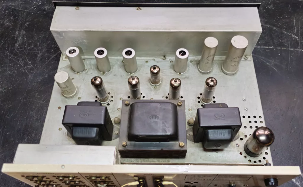
All the tubes are their original Siemens and in good condition, with about 70% emission. It uses the following tubes:
- 2x ECC83: Low-level preamplifiers.
- 1x ECC83: Passive tone control amplifier.
- 1x ECC83: Power stage amplifier.
- 1x ECC82: Phase inverter.
- 4x EL84: Power amplifiers.
- 1x GZ34: High-voltage rectifier.
The CBL transformers are also original and appear to be in good condition, at least visually.
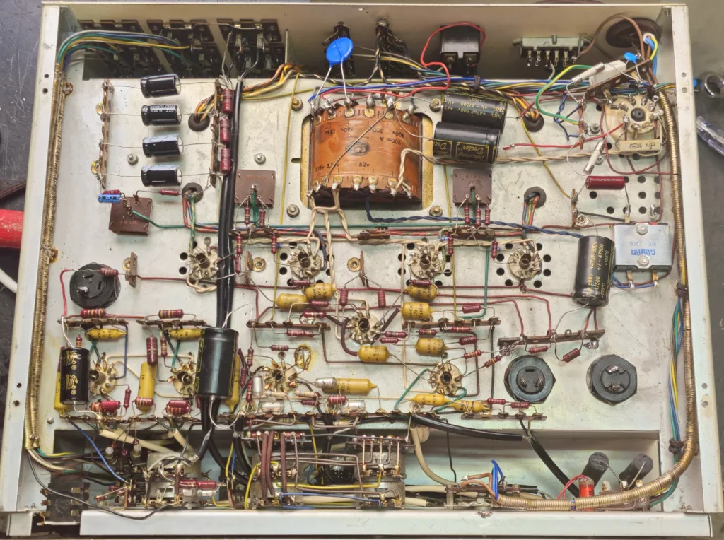
And finally, the circuit:
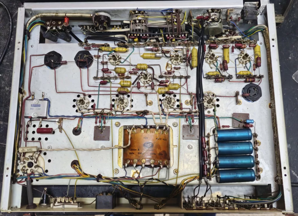
Everything is original and quite well-built.
Tuning Up the Vieta A-215
Once inspected, it’s time to proceed with the actual repair.
The strategy is to replace mainly all defective capacitors, as well as the selenium rectifier bridge. This rectifier generates the negative BIAS voltage and DC power for the preamp tube filaments.
Additionally, all potentiometers will need to be cleaned with contact cleaner to prevent crackling when turned.
As an extra modification, the voltage selector switch should be removed. Nowadays, 125V is no longer used in Spain, and if the switch is accidentally set to this position, it could destroy the power transformer.
Another improvement is to replace the power cord with a modern one that includes a ground connection for added safety. Also, add a varistor to protect the power transformer from voltage surges, as well as extra fuses and protection diodes for the GZ34.
Don’t forget to add 1-ohm, 1% tolerance resistors to the cathodes of the EL84 tubes. This will make it easy to measure the bias current for each tube.
Regarding the capacitors, the yellow ones are Bianchi polyester capacitors. These don’t need to be replaced. Only the electrolytic capacitors need to be changed, and there are quite a few, so… let’s get to work!
And… done!
Unexpected Extra Issues
During the repair, after adding the ground connection to the amplifier, I noticed that sometimes the house’s GFCI circuit breaker would trip when turning on the power switch.
A quick check confirmed that, occasionally, turning the switch caused momentary ground leaks. To fix this, I replaced it with a better switch than the original, taking the opportunity to switch both poles of the mains.
Adjustments, Tests, and Vieta A-215 Schematic
Once all capacitors are replaced and the necessary modifications are made, it’s time to adjust the bias of the tubes.
This amplifier has three adjustments:
- One to set the overall BIAS voltage.
- One for each channel to balance the bias voltage between the two EL84 tubes.
To adjust them, all you need is a multimeter and load resistors at the speaker outputs.
First, decide the current you want to flow through each EL84. Since the voltage is quite high, it’s better to opt for low currents to keep plate dissipation within safe margins. In this case, I chose about 25mA per plate.
The idea is to keep the bias balance potentiometers centered and first adjust the overall voltage potentiometer until you get roughly the desired current in the EL84s.
Then, by adjusting the balance pots, fine-tune so that the current in each pair of EL84s is as identical as possible.
Once this procedure is complete, the amplifier is ready to use, job done, and with a fantastic sound!
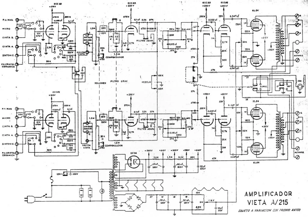
For reference, here is the schematic of the Vieta A-215: