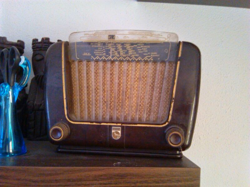
This small radio was brought to me for repair as a birthday gift for a friend’s parents — he wanted to give them the radio in working condition. At first glance, it was clear that the problem would be all the paper and electrolytic capacitors. Also, by looking at the circuit design, it was evident that this is a universal (AC/DC) radio, which comes with the inherent risk that one side of the mains plug is directly connected to the chassis. This means that simply touching any metal part while the radio is operating or even powered off could give you an electric shock.
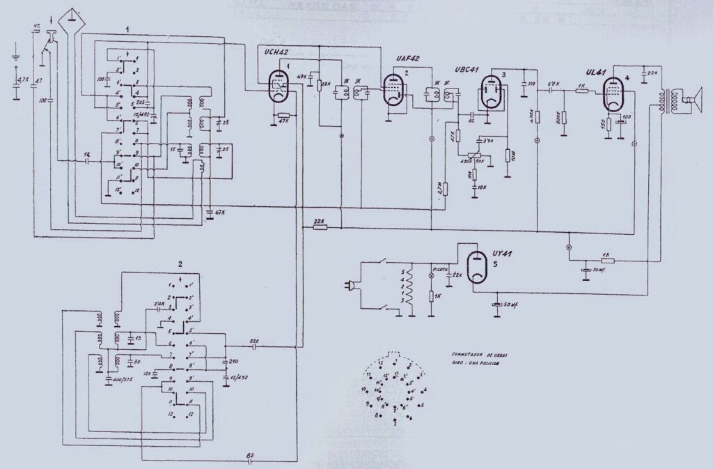
So, during the repair process, an isolation transformer was used for safety. The radio uses the following 5 vacuum tubes:
| UCH42 | Mixer and oscillator |
| UAF42 | Detector and IF amplifier |
| UBC41 | Audio preamplifier |
| UL41 | Audio power amplifier |
| UY41 | High voltage rectifier |
Here it is the radio schematic:
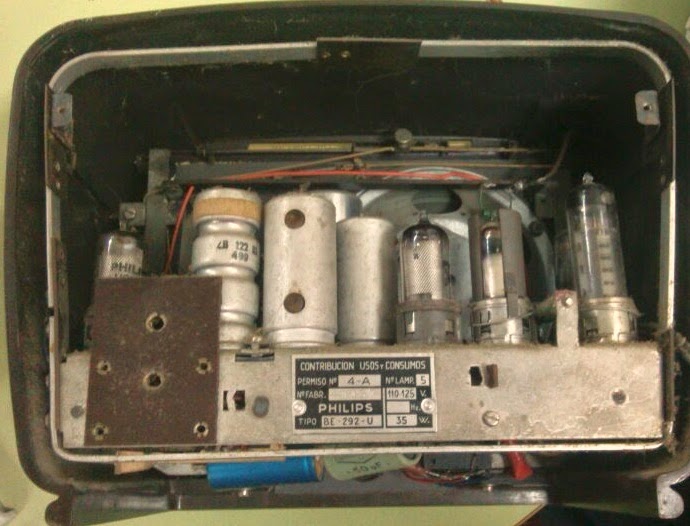
After a quick look at the exterior (which needed a good cleaning), I opened the radio and examined the condition of the interior:
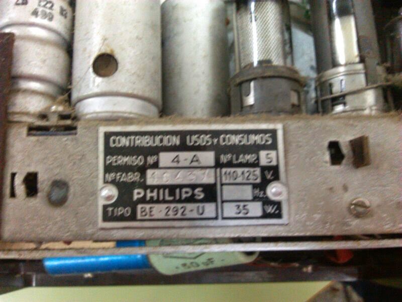
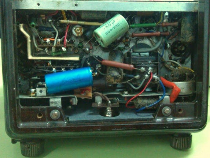
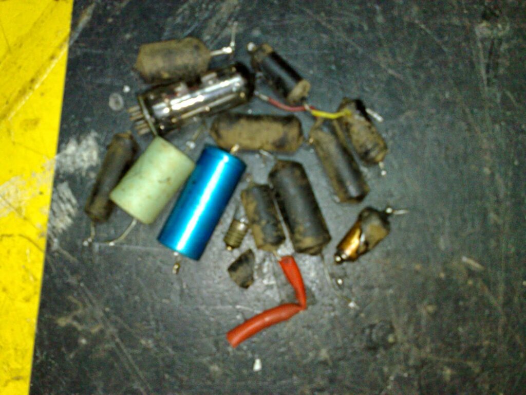
In this last photo, you can see two non-original 50µF electrolytic capacitors, which were undoubtedly added during a previous repair to place them in parallel with the original electrolytic capacitor. By that point, the original had dried out and lost capacity, so adding these two in parallel was a way to compensate for it. However, both of the added capacitors and the original one were faulty, as were absolutely ALL the black paper capacitors — they were moldy, their values unreadable, leaking badly, and some were in such poor condition they literally crumbled in your hands when touched.
Luckily, the output transformer showed no continuity issues, which indicated it hadn’t been damaged by the rectifier.
When removing the tubes to begin extracting the chassis, each filament was checked to see if any tubes were blown — a common issue in these radios when someone tries to power them at 230V instead of 125V. But initially, all the tubes seemed to have intact filaments. During this process, it was discovered that someone had swapped the UAF42 and UBC41 tubes, placing them in the wrong sockets. In that configuration, the radio would never have worked. Naturally, when reinstalling them for testing, they were placed correctly.
Continuing with the checks, the dial bulb was found to be burned out. It was a 19V 0.1A bulb, which is very difficult to find nowadays. To solve the issue, I installed a 125V 3W bulb that fitted into the socket. Since it was slightly longer and the chassis didn’t fit with the new bulb, I used a small spacer to move the bakelite lamp mount back just enough to fit it into the cabinet. This also had the added benefit of eliminating the need for the original 10W ballast resistor used for the dial lamp, saving 10W of wasted heat inside the cabinet.
However, there’s a small downside: since the new bulb is 3W, the front of the cabinet heats up more than it did with the original lamp. This can easily be solved by placing a 1N4007 diode in series with the bulb, effectively cutting the power in half and reducing heat. In any case, I haven’t noticed the additional heat being a serious issue, so I haven’t applied that modification — at least for now.
After replacing every single paper and electrolytic capacitor with modern ones, I proceeded to make a few small modifications to the power supply to improve the radio’s safety. A fuse was added to protect the radio in case of any faults. Additionally, the 22nF capacitor located on the UY41 rectifier board was replaced with a class Y2 250VAC capacitor — a type specifically designed for AC applications. It’s critical not to use a standard capacitor in this part of the circuit, only one rated for safe AC use.
Next, I cleaned the volume potentiometer using contact cleaner spray and powered on the radio — only to be surprised by a small flash from the UY41 and no filament glow at all. I removed the UY41 and found that the filament had blown and the internal cathode-to-pin connection had vaporized. I replaced it with a new UY41, and after installing it, the radio powered up and worked perfectly on all bands, with good sensitivity and selectivity — no further alignment was needed.
Once the chassis was reinstalled in the cabinet, I returned the radio to its owner, who was very happy and ready to gift it to his parents — a happy ending.
These are all the defective components that had to be removed to get the radio working again: