
This interesting radio was given to me for repair by a teacher. She explained that it had belonged to her grandfather, and when it broke down, her mother tried to take it to several places to get it repaired. But she always got the same excuses from those so-called ‘technicians’ who either don’t want to bother or have no idea how to repair a tube radio: ‘That radio can’t be fixed,’ ‘You can’t find the parts for these anymore,’ ‘It’s only good as a decorative piece,’ ‘It’s not worth repairing,’ and so on. Ironically, these radios are actually easier to repair than most modern transistor radios.
And so, it sat as a decorative item for many years — until they heard that I repair radios and brought it to me to see if I could take a look at it. (Though, to be fair, her mother didn’t have much hope, after being told so many times that it was beyond repair.)
The radio has the following tubes:
| 12SA7 | Mixer and oscillator |
| 12SK7 | FI amplifier |
| 12SQ7 | Detector and audio preamplifier |
| 50L6GT | Audio power amplifier |
| 35Z5GT | High voltage rectifier |
When I started checking the tubes, I quickly discovered that a 12SG7 had been installed in place of the correct 12SK7. On top of that, the 12SG7 had an open filament — no doubt once again caused by someone trying to power the radio at 230V instead of the 125V it was designed for. So, I ordered a new 12SK7, and after a few more basic checks, I proceeded to start replacing capacitors.

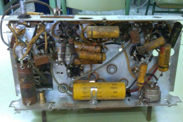
I replaced all the yellow paper capacitors and electrolytics with new ones, as well as nearly all the resistors, which had drifted significantly in value. I cleaned the volume potentiometer with contact cleaner spray, as well as the tube sockets. Since this is a universal radio, I made some basic safety modifications to the power supply.
As a curious note, this radio has a system that allows it to be connected to 230V by changing the wiring of the power cable and adding a special power cord with a series power resistor along its length. These cords are notorious for deteriorating due to the huge heat they dissipate over their lifetime. Moreover, even then, the chassis remains live when connected, and a 230V shock is much worse and more dangerous than 125V.
For that reason, I simply left it connected to 125V with a normal cable (I replaced the old porcelain plug with a new one) and now connect the radio via a 230V/125V isolation transformer, which is much safer and more efficient than the original cord method.
Once I received the new 12SK7, I installed it in its socket, powered on the radio, and after the filaments warmed up… well, here’s what happened:
It works! The radio was functioning perfectly on its bands with loud and clear sound — though it needed an antenna connected, otherwise it received few stations and had low volume.
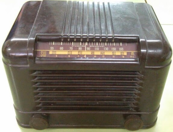
After all this, I put it back into its bakelite case and made a wooden back cover, mainly to prevent people from touching the chassis and to install a banana-type connector for easier antenna connection (previously, the antenna connection was just a bare wire coming out of the antenna coil).
Once that was done, I returned the radio to its original owners, who were surprised and happy to see it working like the first day after so many refusals. Now they use it almost daily with a good antenna and enjoy it to the fullest.
I also recorded another video showing it working inside its case right before handing it over to its eager owners:
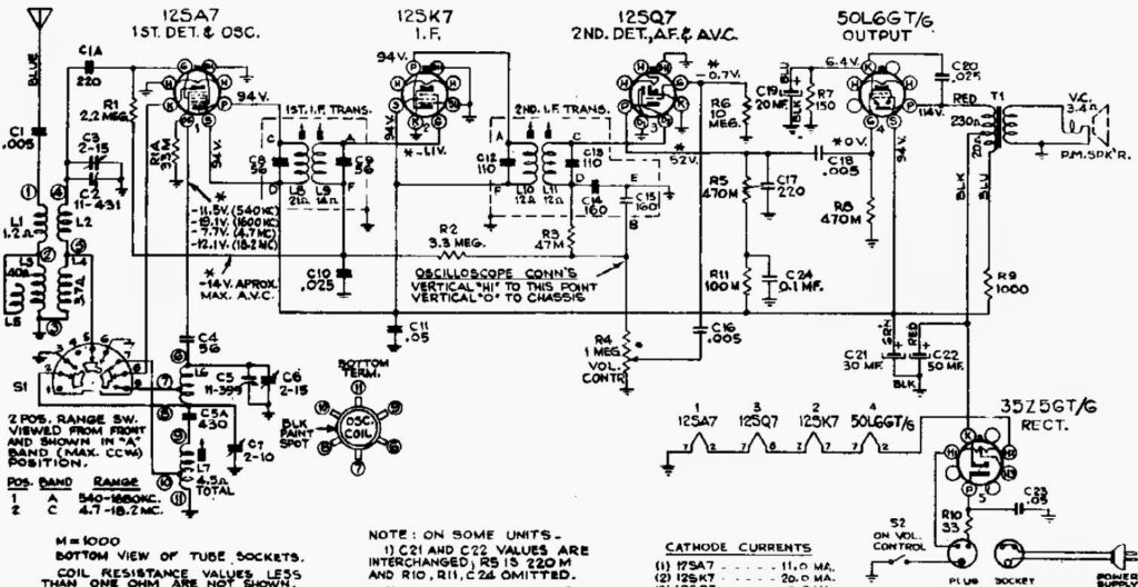
Here it is the radio schematic:
Hola, me llamo Carlos, hace poco conseguí una radio igual a esta y gracias al esquema la pude reparar. Dispongo de una pequeña colección de radios tocadiscos de maleta y disfruto mucho reparándolos y restaurándolos. Saludos.
Hola Carlos, me alegro de que te sirviese el esquema de la radio para reparar la tuya, siempre es gratificante reparar aparatos como estos para que vuelvan a funcionar después de muchos años en silencio. Un saludo.
Hola!!Mi nombre es Berto y soy cubano,tengo 52 àños y desde muy joven,aprendi con un familiar mecanico,a reparar estos tesoros de la tecnologia de antaño!,Es algo hermoso devolver la vida,a un equipo detenido en el tiempo!.Gracias por el esquema!!ojala existieran mas persona como ud!!Salud,Amigo!!.
Hi there, I restored one of these RCA RC594C (or Q10) as well and found the same as you. 🙂 I had to change all the capacitors and resistors as they were not in specification anymore. My radio has a 110V AC connection that does not match the circuit diagram but still seems to work. I have an extra wire going to the transformer on the other side of the chassis. Does your AC circuit just after the AC switch match the circuit diagram?
Thanks for sharing your experience and the videos.
Tony
Hi Tony, I'm glad you liked the restoration of my RCA :). My radio did follow the original schematic, although I changed the circuit a little for safety reasons.
The extra wire of your radio maybe was a modification for some reason, it's a matter of tracing the wire and see what modifications has the radio.
hola tengo un rca solo tengo cha=563A pienso que sea qb55 alguien tendria esquema y fotos por dentro ya legre que funcione AM pero tiene muchos cables conectados donde no tenian que estar fue modificado
gracia mail radiomirabal@hotmail.com
Me llamo pablo y soy de mendoza , yo tambien disfruto mucho de este oficio como hobby, feicitaciones y muchas gracias por compartir tu experiencia.Un abrazo. jppumag@yahoo.com.ar
Desde Moravia,San José, Costa Rica. Saludos fraternos a todos, en especial a EF184, excelente trabajo. tengo un RCA Q10 RC594, identico al que usted restauro y estoy en ese proceso, tengo un problema con el cableado del selector de bandas, ya que alquien anteriormente le elimino la onda corta y yo quiero restaurarla de nuevo. Si alguien pudiera enviarme una foto del alambrado del switch de bandas le quedaría muy agradecido. he seguido el diagrama que usted nos muestra pero se me dificulta ubicar las posiciones en el switch. mi correo es mabol7@gmail.com
Saudações aqui do Brasil. Gostei muito desse artigo e também do esquema e das referecias das válvulas. Muito grato por compartilhar este rico material
yo compre uno igual a esto y lo repare cambiando una valvula y un solo condensador y funciona muy bien.