
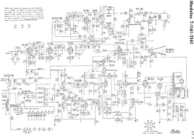
Once I had tested the tubes (and while waiting to get new ones to replace those that were completely dead, as I showed in the first part), I went ahead and took a look at the schematic to see exactly what I was dealing with.
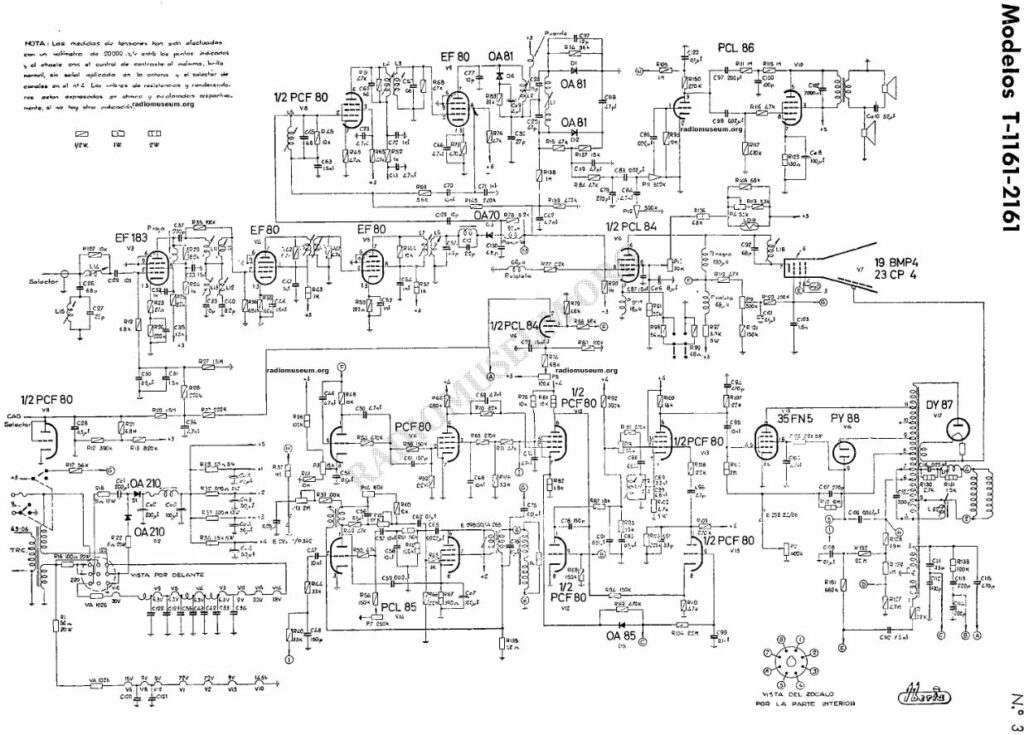
As you can see, the schematic is quite large, which is normal since we’re dealing with something more complex than a standard radio. That means many more stages (and therefore many more chances for a component to fail and make locating and fixing it more difficult 😅).
First Tests
With the schematic in hand, I now had a solid starting point to begin checking the different circuits, so I turned it on again and… 10, 15, 20, 30 seconds go by… the tubes light up, but I don’t hear the line oscillator whine, nor do the CRT or the DY802 filament glow at all… and suddenly a resistor starts smoking 😱.
Naturally, I quickly power it off and start thinking about what might be happening — especially since it had powered on fine before, although with the vertical deflection issue (which I wasn’t too concerned about yet, as I hadn’t replaced any components, and these kinds of things are common — for example, a paper capacitor could have shorted).
The smoking resistor turns out to be R113, located in the power supply section — the very resistor that acts as the filter to supply high voltage to the entire line oscillator section. From this point on, I began replacing most of the paper capacitors in the TV, to eliminate likely suspects.
After swapping out quite a few (not all of them, but certainly the ones most likely to cause trouble), I tried powering it on again and… same result 😞. At this point I realized the problem might be one of the PCF80s in the line oscillator section — they were completely dead, and it’s likely they either weren’t oscillating or were doing so with such low amplitude that the PL300 was drawing too much current, which in turn overheated the power supply’s filter resistor.
Quick test: I swapped some of the PCF80s around, turned it on again and… this time the resistor didn’t smoke, but the PY88 started glowing red hot 😂. Meanwhile, I checked if I had any better PCF80s lying around, and luckily found one. I installed that one in the line oscillator position, powered it on again and… we have a picture!
I had hit the nail on the head — the worn-out PCF80s were indeed to blame. I now had a picture again, although the vertical line issue remained. The bright spot on shutdown was also resolved — the culprit was C116 in the blanking circuit, which was literally destroyed. Replacing it fixed that issue.
As for the vertical deflection, I tried tweaking the height and linearity controls, but all I managed was to stretch the line into a narrow band. Still, better than before.
More problems…
Now that I could (barely) see something on the screen, I noticed the screen showed a completely white raster, with no trace of the usual “snow” you see on analog TVs when they’re not tuned to a channel.
I also realized the channel selector felt a bit loose, so I decided to check it and give it a little wiggle…
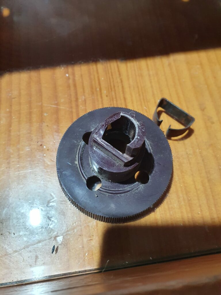
The knob broke, which is a pretty big problem, since the channel selector shaft requires quite a bit of force to turn. Any makeshift repair I try on the knob would likely just break again… That said, it’s not the worst issue, considering analog TV no longer exists nowadays (especially not VHF, which is the only tuner this TV has). So, leaving the knob fixed on the channel I’ll be using to inject analog video, and making sure the control looks good and stays stable on that channel, will be good enough.
As for the audio — the TV was completely silent. I turned the volume all the way up and finally heard the classic crackling sound from a dirty potentiometer, which at least confirmed the audio output stage was working correctly.
To add more to the list of problems, the brightness and contrast controls did absolutely nothing. No matter how much I turned them, the contrast stayed the same and brightness didn’t change at all…
Finding the fault
To stop blindly guessing — since every time I fixed one thing, twenty more problems popped up — I checked the output voltages from the power supply to see if all the voltage rails were working properly and… bingo! On one end of R33 I had 0V, meaning there was no voltage on the +3 rail, which meant the entire video reception and amplification circuit was completely dead.
So I checked continuity on R33…
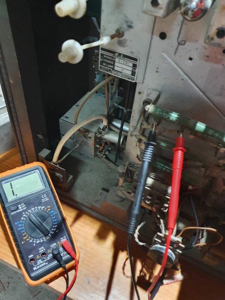
There’s no continuity at all — it’s completely open, so it has to be replaced. Since 600Ω isn’t a standard value, I used two 1.2kΩ resistors in parallel instead.
As I didn’t have any 1.2kΩ resistors on hand, I temporarily installed a 620Ω one salvaged from another device. Since it’s a bit higher in value, the whole +3V rail will get slightly less voltage than expected, but it’s enough for testing.
After powering it back on and waiting… same results. Although I now measure voltage in that part of the circuit, the reception section still shows no trace of static, and the audio is still absent — although this time, there’s the occasional bit of background noise.
At least the brightness and contrast controls are now working properly, so that part is resolved.
Without replacing the remaining PCF80 tubes, along with the dead EF183, I doubt I’ll get much further in this area — so it’s time to shift focus and see what’s going on with the vertical deflection…
I’m not the first to take a look at this TV
Let’s now take a closer look at the PCL85 circuit:
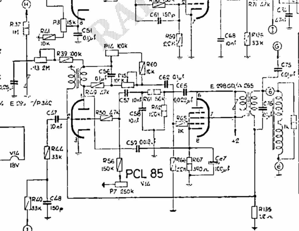
It’s not an overly complex circuit. Essentially, it’s a class A “audio” amplifier that’s been specially optimized to amplify just one frequency — the 50Hz of the vertical refresh rate — and its load isn’t a speaker, but rather the vertical deflection coil mounted on the CRT’s yoke.
The triode section basically works as a blocking oscillator that generates a 50Hz sawtooth waveform. The vertical sync signal from the received image is fed into it to ensure both signals match exactly in frequency, so the image appears “stable” on screen. Otherwise, it would vertically “roll,” so there’s a vertical sync adjustment potentiometer to manually fine-tune the local 50Hz signal in case it doesn’t lock onto the demodulated sync pulse.
On the other hand, the pentode section receives this 50Hz signal and amplifies it. The height control acts like a “volume” control in this case. It’s also important for the signal to be amplified linearly, otherwise the image would look distorted on screen. That’s why the stage includes feedback and a “vertical linearity” adjustment that simply changes the amount of feedback.
Unlike a typical audio amplifier, this one includes some “special” components called VDRs (also known as varistors) — resistors whose value changes with the voltage applied across them. You can spot their symbol in parallel with the vertical output transformer in the schematic. Their purpose is to dynamically adjust resistance during sudden waveform transitions and protect the transformer from dangerous voltage spikes that could damage it.
While carefully inspecting the circuit, I started replacing resistors that had drifted too far out of spec and noticed someone had previously tinkered with this section, especially around the adjustment potentiometers.
Looking at R39 and R37, which influence the height control, I found that R39 had this value installed in the set:
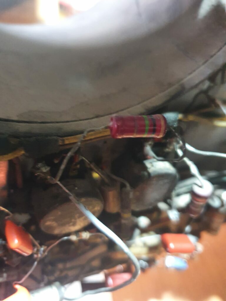
The resistor was 1MΩ instead of the 100KΩ shown in the schematic 🤦♂️. And R37, which should have been 1MΩ, was actually 3.9MΩ. Naturally, I replaced these with the correct values as specified in the schematic. I also discovered that other areas had incorrect resistor values too — for example, the screen grid resistor of the PL300 was 2.7KΩ instead of the 2.2KΩ it should have been.
In that case, even though the difference is small, it can still have an effect: a higher value means less voltage reaches the screen grid of the horizontal output valve, reducing the current it can deliver when the stage saturates. This can result in less flyback transformer output and lower booster voltage, which in turn can cause the screen to appear dimmer than it should.
For now, I haven’t replaced any other “altered” resistors besides the ones affecting the height control. After powering it back on and adjusting potentiometers P13, P14, and P15 a little:
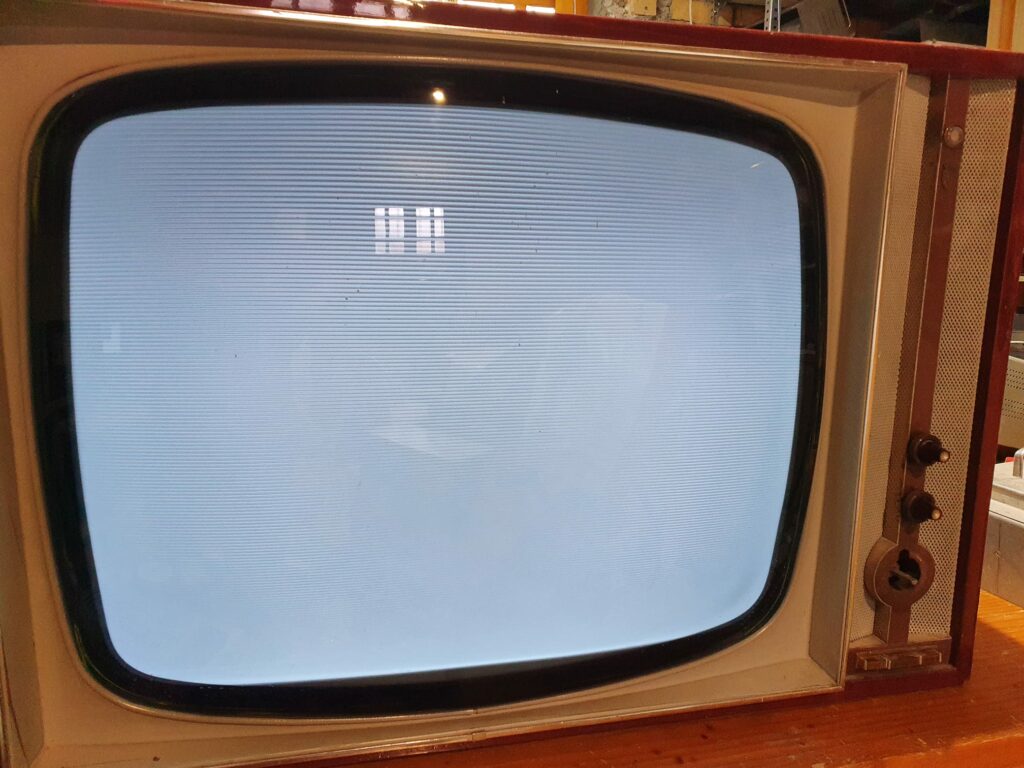
At last, the screen now has full vertical deflection 👏. That said, it only happens with all the controls pushed to their limits, and even then, there are moments when the lower part of the screen briefly loses deflection — so this story isn’t over yet, and more troubleshooting is needed…
I find it puzzling why someone replaced those resistors with such incorrect values, especially since it was obvious that full vertical deflection would never be achieved with them. My theory is that whoever tried to repair the TV before probably didn’t have the schematic, and the original resistors were too dirty to read their values clearly. So they likely replaced them with what they guessed were the right ones. And when they saw the problem persisted — or that there were even more issues in other parts of the set — they probably told the owner it wasn’t worth repairing and suggested getting a new TV instead.
UPDATE: After a few months’ break, I tried to resume the restoration, but unfortunately the picture tube has taken in air somehow, rendering the TV completely unusable. These days, finding a replacement CRT is almost impossible — and when you do find one, it’s rarely affordable — so I’ve had no choice but to consider the restoration a failure. Still, I’ll salvage many useful components during the recycling process, which will certainly come in handy for many future projects. So in a way, this TV will continue to be useful — even after being dismantled.