

A few days ago, a reader of the blog contacted me asking for help figuring out why a vacuum tube AM transmitter circuit he had built—following the instructions from an electronics website—wasn’t working properly.
After analyzing the circuit he built, I wasn’t at all surprised that it didn’t work. In fact, unknowingly, he had wasted both time and money building a transmitter whose so-called “design”—if it can even be called that—makes no sense whatsoever. We’re going to break it down in detail now, so that no one else falls into the same trap in the future.
The circuit in question is from this page: “Personal AM Transmitter“, and its schematic is shown in the following image:
Just by glancing at the schematic, you can spot several errors. For example, the tube symbols are drawn incorrectly: the 6AV6 is actually a triode-double diode, not a pentode as shown. Also, the other tube isn’t a 6AQ6 (another triode-double diode), but a 6AQ5 — an audio power pentode essentially like a 6V6 but with a max plate voltage limited to 250V. The symbol used is somewhat acceptable but not entirely correct, since the 6AQ5 is a beam tetrode, not a simple tetrode.
Looking further from left to right, things get worse:
- What’s the point of having that transformer at the input? It might make minimal sense to provide galvanic isolation between the audio input and the circuit, but since the power supply already has a transformer and it’s not a “universal” (direct AC) supply, it’s unnecessary.
- To paraphrase the original text: “The audio signal needed to drive the system can come from a low power amplifier (like an LM386) or from the headphone output of any recorder.” This hints that the transformer’s purpose is to match the LM386’s output impedance to the tube input. But this makes no sense — it’s absurd to inject an amplified output signal because the input should only be a small signal of a few volts peak-to-peak, which the 6AV6 will amplify.
- Focusing on the audio preamp stage with the 6AV6, the drawing is incorrect, though the pins correspond properly to the 6AV6. Anyone with some experience with typical 6AV6 circuits would be horrified. Why? Because it’s running without bias voltage.
- The idea was to use “contact bias,” where the cathode is grounded and electrons leaking naturally to the control grid generate a negative voltage near -0.7V, biasing the stage. But to achieve this, the grid resistor must be very high, typically around 10MΩ. Here it’s only 1MΩ, which doesn’t generate enough bias, leaving it almost at 0V. The result: any audio signal fed to the preamp gets distorted, making it impossible for the transmitter to sound good.
- Also, the 6AV6 is a high-gain tube. Assuming the bias issue is fixed, the circuit amplifies the input signal roughly 60 times, and the output stage only needs about 10V peak-to-peak drive to modulate fully. So the input audio signal should be at most 0.16mV peak-to-peak; higher levels will cause overmodulation.
- Another problem: the schematic doesn’t show any voltages or currents. By theoretical analysis, the supply should be about 170V at 26mA.
- One last note on the preamp: there’s no high-frequency roll-off. Remember that AM audio bandwidth is about 10kHz max, meaning frequencies above 4.5–5kHz should be filtered out to avoid wasting spectrum and interfering with adjacent broadcasts. This circuit amplifies all frequencies without limit, which could cause excessive bandwidth and interference. However, it might benefit receivers with wide bandwidth (like crystal radios) by preserving fidelity.
- Now, on to the output stage — WTF! A self-oscillating power stage modulated directly by the control grid. This causes simultaneous AM and FM modulation, resulting in severe distortion at the receiver.
- Because the oscillator feeds the antenna directly, any change in antenna conditions (like moving nearby or wind) will shift the transmission frequency, as will temperature or supply voltage changes.
- The author describes the oscillator coil as “100 turns of AWG28 wire with a center tap (50 + 50 turns) on a 1-inch plastic tube.” Doing the math: 1 inch = 2.54cm, AWG28 = 0.8mm copper wire. The coil inductance is about 69µH. The variable capacitor isn’t specified but typical MW capacitors range from about 33pF to 410pF max.
- Calculating frequency range with a 410pF cap gives roughly 1MHz to 3.3MHz — which doesn’t cover the lower MW band and extends nearly to the 80m ham band, which is illegal unless you’re licensed.
- A simple fix: increase the coil inductance by adding turns — for example, about 318 turns would give roughly 238µH, covering the proper band.
- Also, the variable capacitor isn’t really needed if you want a fixed frequency; a fixed capacitor between 30pF and 470pF could set the frequency, simplifying the design.
- The LC oscillator design has practical issues: the variable capacitor is at high voltage on both terminals, requiring perfect isolation from chassis, making mounting tricky and dangerous (touching it means touching 170V).
- No harmonic filtering or antenna impedance matching is present, so radiated power is low and many harmonics go unattenuated. Since the antenna is short, higher frequency harmonics will radiate better than the fundamental, causing interference. This page has useful info on how to fix these problems.
- Because it’s a self-oscillator modulated directly, the tube must operate in class A bias, limiting output power further. The 10µF cathode bypass capacitor is too small to fully bypass low frequencies; 100µF or more would be better.
- Calculations show the 6AQ5 cathode bias is about -10V, drawing roughly 25mA, slightly more when including screen grid current.
Overall, this circuit is a disaster.
Next, let’s analyze the power supply…
- Those 8µF capacitors have a very low capacitance, typical of radios from the 1930s. Using such values today makes no sense, and since the circuit rectifies with diodes, I would suggest using capacitors of at least 100µF.
- The 100nF capacitor in parallel with the 8µF one is unnecessary; it serves no real purpose. Originally, the idea behind placing that capacitor in parallel was because electrolytic capacitors back then had poor ESR, especially at high frequencies, so it was needed. With modern electrolytics, this is no longer required.
- The 1kΩ resistor in the pi filter feeds both the preamp and the oscillator. This is very bad practice as it causes positive feedback in the audio preamp. Adding another resistor-capacitor network to feed the preamp at a slightly lower voltage than the oscillator would avoid this effect.
- Since the oscillator’s supply voltage is critical to maintain frequency stability, I would recommend regulating that voltage with Zener diodes or voltage regulator tubes. Also, there’s no problem using a rectifier tube instead of 1N4007 diodes if desired; just ensure the first filter capacitor does not exceed the rectifier’s datasheet maximum rating.
- There is no capacitor across the tube filaments, which can cause some RF generated by the oscillator to leak into the preamp tube via the filament circuit. Although at these frequencies this might not be a serious problem, adding a capacitor of about 10nF or more wouldn’t hurt to avoid possible issues.
- According to the author: “The power supply, seen above, is built around a somewhat odd transformer. It consists of a 200V primary (or the mains voltage where the equipment will be used) and two separate secondaries. One must supply 6.3V for the tube filaments. The other secondary must be 300V center-tapped (150 + 150V), used for the high voltage supply for the tubes.” Calling the transformer “somewhat odd” clearly shows the author has never seen a typical valve equipment power transformer. Anyway, if this “odd thing” bothers you (and as a useful tip for those who don’t have such a transformer), you can connect two 230V/6V transformers back-to-back to get both the filament voltage and a galvanically isolated 230V secondary. In that case, replace the two 1N4007 diodes with a bridge rectifier using four 1N4007s and adjust the pi filter resistor to drop the voltage down to the 170V the circuit requires.
- Continuing with the author’s words: “Remember all capacitors should have twice the working voltage rating. So if the transformer outputs 300V, the 8µF capacitors must be rated 600V.” This statement shows the author has never worked with these transformers and/or doesn’t understand how the rectifier circuit works. It’s a full-wave rectifier, essentially the same as a diode bridge but with a center-tapped secondary, saving two diodes. The output voltage after the diodes would be like a normal bridge rectifier connected to a 150V secondary. The peak voltage the capacitors must withstand is about 212V, so capacitors rated at 250V minimum are sufficient. Specifying 600V is an exaggeration, and today such capacitors are rare and expensive.
- Of course, if you do the modification I mentioned above (using a 230V secondary), the capacitors would need to handle at least 350V.
To close the article, the author tells us the following:
“The output tube can be replaced by: 6L6, 6AQ5, 6V6, among others. But always keep in mind that the pinout is different, so you will need to consult the manuals (if they still exist).”
To begin with, you cannot just swap the output tube for whichever you want without checking the cathode resistor to properly bias the new tube, and most likely you would also need to adjust the supply voltage. The statement in bold reveals the author’s complete lack of knowledge about tubes.
Fixing the circuit a bit
Despite everything, I took the trouble to modify all the mistakes in the schematic, mostly for educational purposes, because although this new version would certainly work, the circuit still has design problems that would only be solved with a radical redesign.
List of changes and improvements:
- In the input stage, I added a 47K potentiometer (it must be logarithmic) to control the modulation level, since, as I mentioned earlier, the input signal must be adjusted to avoid overmodulation.
- The preamplifier stage has been changed to use negative feedback and also implements a first-order low-pass filter to cut input frequencies above 5 kHz. The gain of the feedback stage is approximately 16, so with around 0.5 Vpp input, it should be able to achieve full modulation. Additionally, the feedback helps reduce distortion in the amplified signal.
- The tube symbols have been redrawn to reflect the correct schematic symbol. Technically, the 6AQ5 is not a pentode as shown, but I left it that way to avoid spending too much time on the drawing.
- The 6AV6 biasing has been corrected; it now uses diode bias. The diode can be any with a forward voltage around 0.7 V, such as a 1N4148 or even a 1N4007.
- As an extra note, the 6AV6 can be perfectly replaced (if necessary) by one half of an ECC83, since they are essentially the same triode. The 6AQ5 can be replaced without changes by the 6V6 or, if preferred, by its noval version, the 6BW6. These replacements are fine since they are electrically equivalent and do not require rebiasing.
- The cathode bypass capacitor of the 6AQ5 has been increased to better decouple low frequencies.
- Although I haven’t changed the cathode resistor value, it would be advisable to try other values to see whether changing the bias point improves or worsens the signal. I suspect the current value might not be optimal. Since I won’t be building the circuit (and again, I recommend no one does), I can’t confirm whether another value would work better.
- It still has issues like FM modulation, frequency instability, harmonics, and the carrier leakage problem, but at least now it would do something — unlike the original version, which was a complete mess.
Building the improved circuit
To demonstrate just how bad the circuit is — even in this “improved” version I just designed — I went ahead and sacrificed my time to build it quickly, just to show why you shouldn’t waste your own time building this transmitter.
I used an external power supply for more flexibility while testing and also to avoid the hassle of building a dedicated power supply for a circuit I already know is going to fail.
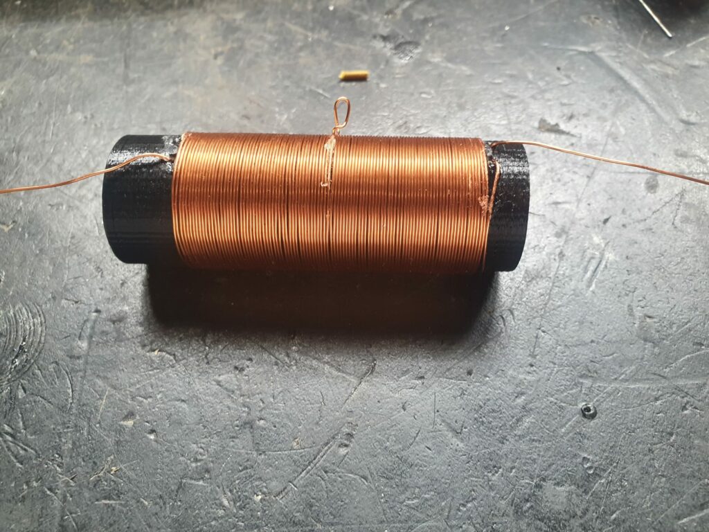
As for the oscillator coil, even knowing that the one described in the schematic doesn’t allow transmission below 1 MHz, I decided to replicate it roughly as described. I used 0.5 mm enamelled copper wire instead of 0.8 mm, simply because it was the closest I had at hand.As for the shape of the coil, I designed it quickly and 3D printed it:
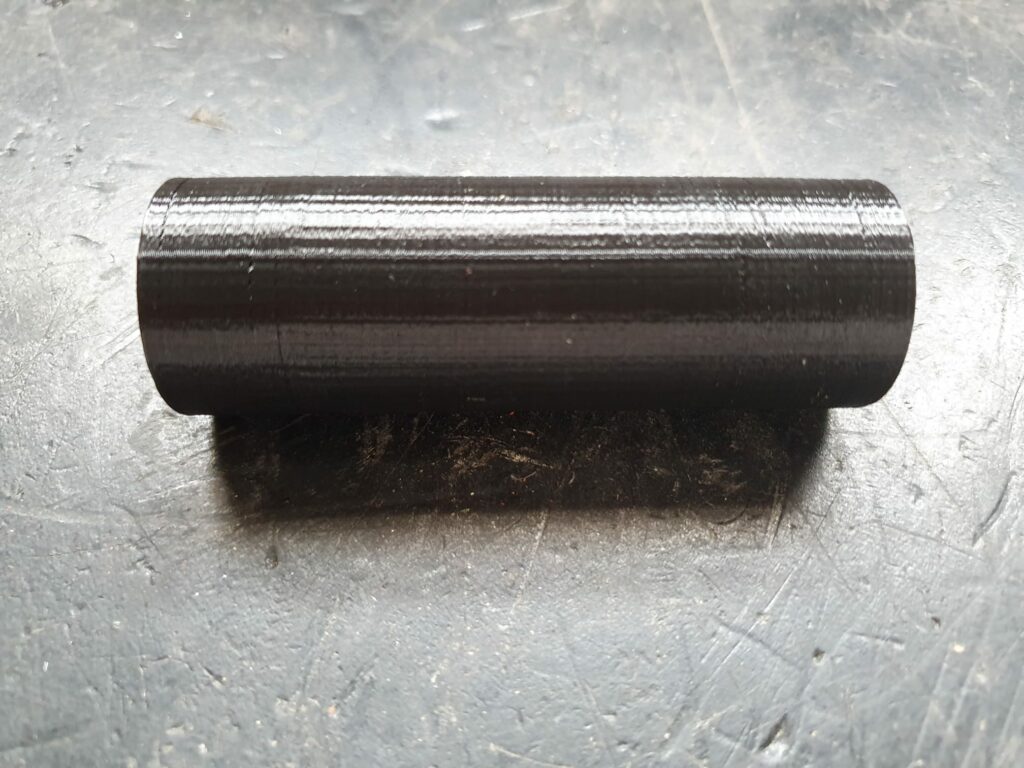
It has a diameter of 2.55 cm and is about 7.5 cm long. I didn’t design holes for the wire because it was easier to make them on the spot with a punch.
Once 3D printed, I wound the 100 turns with a center tap as the article says. For the center tap, I just tied a small knot at turn 50, and to keep the windings firmly in place, I applied a bit of glue.
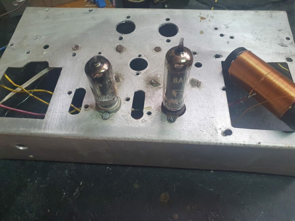
Once the coil was finished, I built the rest of the circuit in no time. Instead of using the 6AV6, which I didn’t have on hand, I used a 12AV6 — it’s the same tube but with a 12.6 V filament. For the chassis, I reused one from a scrapped radio to take advantage of all the small holes that were already there.
Once the circuit is finished, I attach a long piece of wire as an antenna, connect the oscilloscope to observe the modulation, inject a 1 kHz tone from my phone as the audio signal, and:
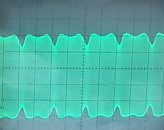
As expected, the modulation was terrible—even with the improved audio preamp circuit.
Using the oscilloscope, I found that all the distortion comes from the output stage. The previous stage amplifies the signal with the roughly theoretical gain of 16, with perfect fidelity and a proper high-frequency cutoff. From the waveform, we can see the modulation index is quite low. When tuning in with a radio, the distortion is noticeable, although overall the sound is “acceptable.”
Out of curiosity, I modified the circuit to match the original article exactly. The result was awful. As I anticipated, the signal was far more distorted, and on nearby receivers it sounded terrible—almost unintelligible.
Another weak point was the harmonics. As discussed earlier, the transmission frequency couldn’t drop below 1 MHz—but that didn’t matter, because there were harmonics all over the place.
Transmission range was also very limited—maybe 100 m at best—and very dependent on the antenna’s orientation. Again, this was expected. A longer antenna might have extended the range slightly, but it wasn’t worth trying.
Other similar designs
Finally, if you search around the internet, you’ll find many variations of this circuit with subtle differences. For example, there’s the 4 W transmitter circuit from the brand Daxon:
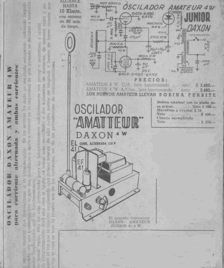
If you take a closer look at the circuit… surprise! It’s exactly the same circuit, with some changes in the power supply and a few component values. At least this version should work better than the one we’ve been analyzing.
If we dig a little further…
…We find a circuit that’s even worse than the first one — here they’ve gone so far as to remove the grid leak resistor from the 6AV6, meaning once again there’s no BIAS on the preamp stage.
In conclusion, I don’t think the people who published these circuits did so with bad intentions. They probably just copied the same kind of schematic with some modifications, and along the way ended up copying things incorrectly — like wrong component values and other issues.
For those interested in building a small AM transmitter using vacuum tubes, I’m finalizing a better-designed circuit than these ones. Like everything, it has its drawbacks, but it’ll be published on the blog soon, so stay tuned.
Meanwhile, as advice for anyone wanting to build a small and simple AM transmitter — but one that’s infinitely better than this — I recommend the one described on this page. The 6CQ8 tube can be directly replaced by a PCF82/ECF82, which might be easier to find than a 6CQ8.