
This small amplifier project began thanks to a blog reader, Sergio, who contacted me via email to see if I could help him design a small guitar practice amp using some parts he had salvaged from old radios and record players. The goal was a compact 3 to 5W amplifier, ideally with a tremolo circuit. After sending me several photos, we got to work… 😉
Among the tubes he had recovered, we chose the ECC81 (12AT7) and the ECL86 (6GW8). Nowadays, the ECL86 is becoming increasingly rare and hard to find, so if anyone wants to build this amp but doesn’t have one, a PCL86 can be used instead (they’re more common), provided the filament is powered with around 13V. In this case, a 12V transformer can power both valve heaters: by leaving pin 9 of the ECC81 unconnected and supplying pins 4 and 5, you can feed it with 12.6V, which works perfectly with the PCL86.
We were also lucky to have a 7K output transformer with its speaker, a 230V mains transformer with suitable voltages for the build, a 5H choke to help reduce ripple, and some sockets and components that would come in handy. If you don’t have a proper choke, a 470Ω 2W resistor can be used instead—though 5W is even better.
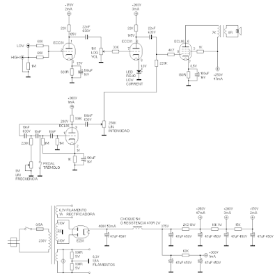
Once all the needed parts were gathered, I got to work on the schematic. After calculating some load lines, currents, and simulating the power supply, the circuit was ready to be built 😁. Let’s break it down stage by stage.
1. Preamplifier stage
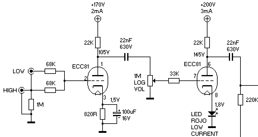
The preamplifier stage is implemented using an ECC81 instead of the more typical ECC83 (12AX7), simply because that was the tube available. Also, using an ECC83 would have resulted in too much gain, causing distortion too early, which Sergio wanted to avoid, so the ECC81 was quite suitable for this purpose.
As we can see, there are two guitar inputs: Input 1 (HIGH) which provides maximum gain, and Input 2 (LOW) which, when connected, causes the 68K resistors to act as a voltage divider that halves the pickup signal, thus reducing the gain as desired.
The first triode of the ECC81 functions as a standard gain stage. The bias is roughly centered to allow maximum amplification before distortion sets in. If desired, gain can be slightly reduced by disconnecting the cathode bypass capacitor, which introduces negative feedback to decrease gain and distortion at this stage.
The second triode of the ECC81 is a bit special 😉. Instead of using a resistor and capacitor on the cathode for biasing, we used a low-current red LED.
This has advantages such as maximum amplification at low frequencies and fewer components. It’s important that the LED is red, which ensures a bias of around 1.8V during conduction (so this stage is biased not in the middle like the first one, but closer to the 0V curves, producing a bit more distortion), and that it is low-current.
A typical red LED requires about 10mA to fully light up and stabilize the bias at 1.8V. In this stage, the current through the LED will be about 3mA, so to keep the 1.8V bias as stable as possible, a low-current LED is needed.
As a final note, we chose not to include global negative feedback because it would reduce overall gain and distortion — a desirable feature in a very clean amplifier (essential in HiFi), but in this case we want a good distortion when desired.
2. Power stage
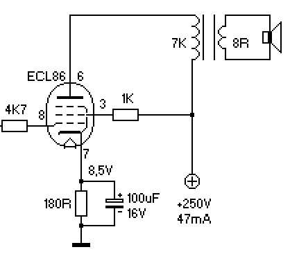
The power stage is quite conventional. The pentode section of the ECL86, with 250V on its screen and anode, and biased with a 180Ω resistor, is capable of delivering up to 4W of power at 10% distortion with only 3.2 VRMS at the input.
In reality, it will deliver slightly less than 4W due to losses in the output transformer and because there is a 1K screen resistor, which under maximum signal conditions causes the screen voltage to drop below 250V, resulting in less power but also less distortion — which is what we want 😊.
We also inject the tremolo signal directly into this stage through the 220K grid stopper resistor. This is the circuit we will discuss next:
3. Tremolo circuit
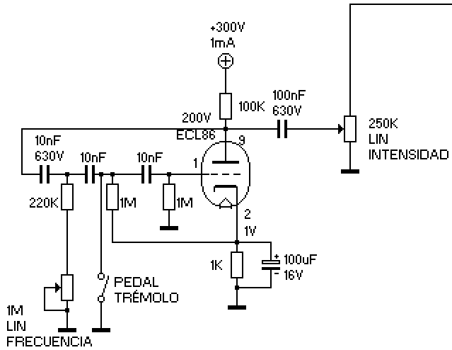
The tremolo circuit is very conventional and taken from the ValveWizard website, a great site I recommend visiting, which explains this circuit in quite some detail.
For this circuit, we use the triode inside the ECL86, which is identical to an ECC83 triode. We feedback it to form a low-frequency oscillator, whose frequency is controlled by the 1M linear potentiometer in the circuit.
The tremolo is turned on or off by a footswitch (or a front panel switch, whichever you prefer) that connects, as seen, the capacitors in the grid feedback line to ground. When the switch is pressed, it sends the oscillator signal to ground, preventing it from oscillating and thus stopping the tremolo. When not pressed, the feedback signal is uninterrupted and the tremolo works.
The tremolo depth (its “volume”) is controlled by the linear level potentiometer shown in the circuit, whose top end connects to the 220K resistor in the power stage. This couples the low-frequency signal more or less to the ECL86 pentode grid, mixing the low-frequency signal with the signal previously amplified by the preamp stage.
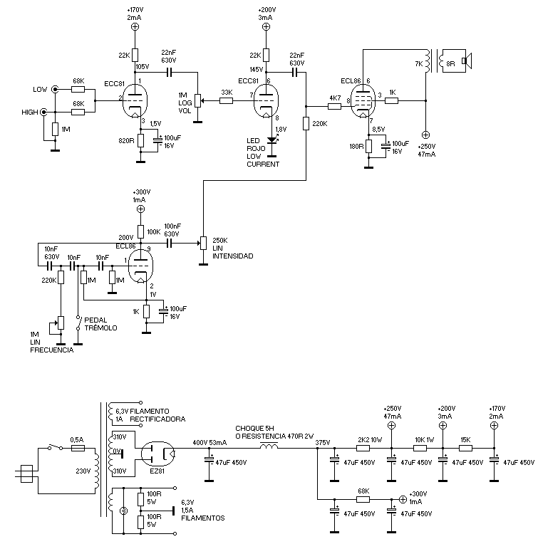
4. Power Supply
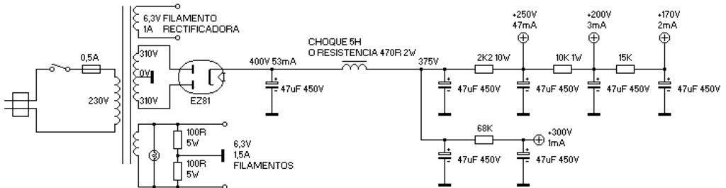
The power supply is where you can have the most flexibility, given the endless possibilities to feed each stage of the amplifier.
We had a transformer from an old radio that ran on 220V and had a high-voltage secondary of 310-0-310V, as well as a 6.3V and a 4V secondary that we didn’t use (undoubtedly intended for a directly heated rectifier like the AZ1 or AZ41). Sergio decided he wanted to use an EZ81, although he didn’t have one, so he bought a new JJ one and I designed a circuit to use it.
The EZ81 is powered from the same winding as the other filaments. This is not recommended but since we had no other option, we used it this way. In fact, in the schematic, you can see how I drew it with its own 6.3V secondary separated from the other filaments to avoid any confusion.
In the filament secondary, there are two 100Ω 5W resistors to ground in each branch. This provides a ground reference to the filaments and prevents hum.
Since we had a choke, we used it. The choke allows the ripple of the power supply to be much lower than using a resistor, although if you don’t have a choke, you can use a 470Ω/2W resistor (5W better) to simulate it. Although the ripple will be higher than with the choke, the good filtering done in the following stages will mean it doesn’t make much difference.
Each stage of the amplifier is fed at a different voltage and with a minimum 47µF capacitor. This ensures that there is practically no ripple and also prevents coupling and oscillations between stages caused by a poor power supply design. In fact, many small valve amplifiers of this style have an incredible lack of filtering which causes all sorts of problems (few capacitors and very low values). That made sense many years ago when capacitors were expensive and bulky and speakers had very limited frequency response, which mitigated oscillations and hum somewhat, but it is totally unacceptable nowadays.
The power supply can be improved in many other ways besides those mentioned. For example, you can replace the EZ81 with diodes, or use 12V filaments to use the PCL86 with the ECC81, you can use a transformer that delivers less AC voltage (you would need to recalculate the supply but it would be better because less energy would be wasted in the resistors), or even if you don’t have a transformer with those characteristics, use back-to-back transformers, for example 220-12V or 220-6V (depending if you want ECL86 or PCL86), and rectify the 220V with a bridge rectifier (again a simple modification in resistor values of the supply would be needed for the lower AC voltage available).
5. Conclusion
After designing the circuit, Sergio built his amplifier which he named “The Wrecked Amp.”
Some complications arose during assembly: For example, the JJ EZ81 died with a short between the cathode and the filaments which, through the 100Ω resistors, grounded the HT line causing the input fuse to blow repeatedly, something that took us a while to figure out but we finally discovered and Sergio had no choice but to buy another EZ81. Also, the tremolo didn’t work at first due to a small wiring mistake, which we also eventually fixed.
However, in the end everything went well and the amplifier worked perfectly, plus we added improvements like a switch to bypass the first triode to greatly reduce gain. Sergio was very happy with the amplifier 😁. With his permission, I’m sharing some photos and videos of the build:
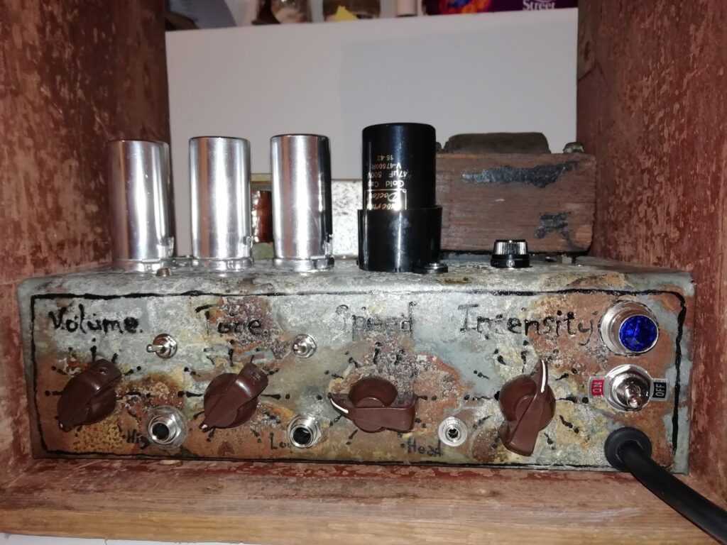
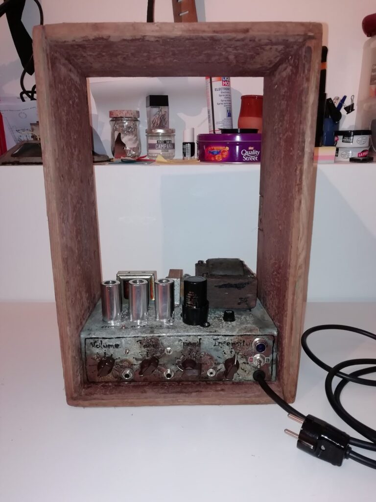
I really like the amplifier’s aesthetics, and it looks great in that cabinet too.
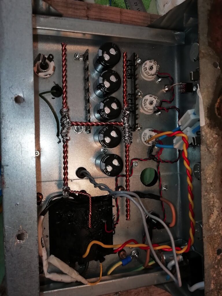
Here I was assembling the filament circuit. Notice the ground bus — it’s very well done, with bare copper of large cross-section, ensuring no issues with the ground returns of the components.
Finally, here are a few short videos of how it sounded once finished:
A video showing the tremolo in action:
I hope you’ve enjoyed this amp as much as I enjoyed designing it and Sergio enjoyed building and using it 😉