
This small single-tube transmitter is designed to broadcast any audio source on the AM band, so that various programs can be heard on all old radios that only have the standard AM band and no FM.
For this, I chose a PCL805 tube, since I had a few on hand and wanted to put them to use. Of course, similar tubes can be experimented with without any problem, keeping in mind that depending on the type, the supply voltage may need to be changed because not all tubes can handle the 300V that the PCL805 can withstand.
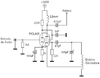
As you can see, the circuit is very simple. The triode section of the tube is used as a simple audio amplifier triode, with the particularity that it is connected directly to the pentode screen without using the typical coupling capacitor. The pentode section is used as a Hartley-type oscillator, with a coil having a center tap that, together with the variable capacitor, determines the transmission frequency.
For the AM band, the coil can be made on a 35mm diameter cardboard tube, wound with 120 turns of 0.3mm enamelled copper wire, with the center tap at the 40th turn. Changing the number of turns of this coil allows transmission on different bands. In my case, I used the oscillator coil from an old transistor radio I dismantled some time ago, so the transmission range I have is approximately from 1MHz to 2MHz, allowing transmission in the upper part of the AM band and even in the 160m band.
The pentode is screen-modulated with the audio signal previously amplified by the triode, and the modulated signal is sent to the transmitting antenna. Since the impedance is not properly matched, it will transmit with less power than it could if properly coupled.
IMPORTANT NOTE: Due to the simplicity of the design, this transmitter will not be very stable and will modulate in frequency as well as amplitude, causing annoying distortion. Also, the method of modulating the screen with the triode output will not produce 100% modulation and will generate quite a bit of distortion. However, it is a quick and easy design to implement, and if high requirements for sound quality and range are not needed, it works perfectly. Still, it is much better than other simple designs found on the internet that perform worse or don’t work at all.
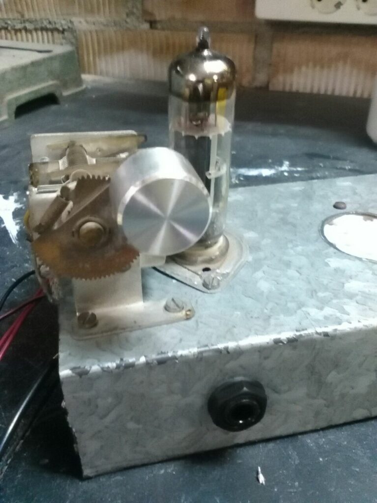
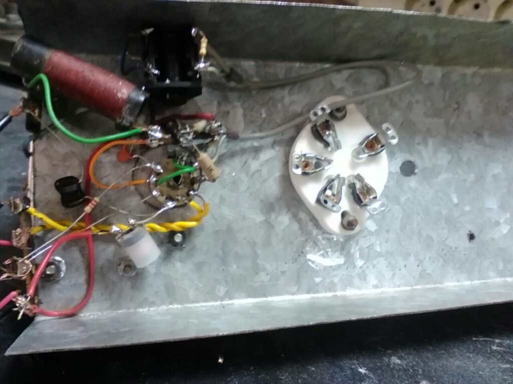
Here are some images of the assembly:
The transmitter’s current consumption is 33mA without an antenna connected, and with a 2-meter improvised wire antenna, the current consumption drops to 14mA. The transmission range with this antenna is good; the signal could be clearly heard in every room of the house, with a maximum range of 50 to 100 meters without problems.
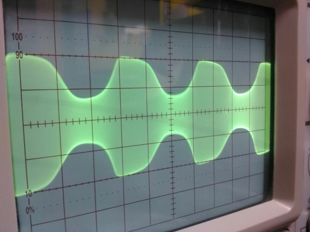
Using an oscilloscope, the waveform at the antenna output without an antenna connected was measured:
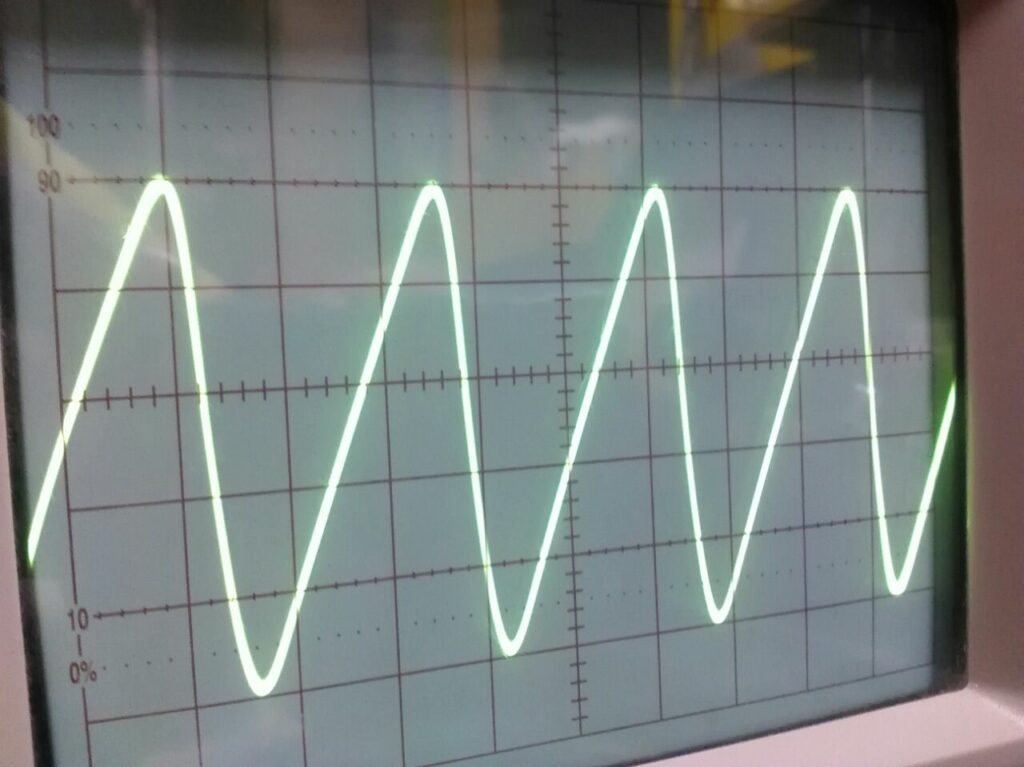
The amplitude is about 20V peak-to-peak. Then, using a 400Hz test signal from a valve RF generator, I checked the maximum modulation it can achieve before distortion begins, which is around 60–70%. (In the image, keep in mind that the waveform looks like that because the generator I have outputs such a distorted waveform.)
To achieve the maximum modulation level, an audio signal of 3V peak-to-peak is needed at the triode input. This signal can be easily obtained from old ceramic cartridges of turntables or from a carbon microphone. However, to connect modern audio sources like a mobile phone, computer, etc., another preamplifier will be required to boost the weak audio signal to the 3V peak-to-peak needed. For this, a small transistor preamplifier or a tube preamplifier can be used.
Of course, the design can be improved — for example, by adding another tube to act as an audio preamplifier, stabilizing the power supply voltage, adding a pi filter to better match the antenna, and so on. But for the use I’m giving it, as it is, it’s an easy and simple circuit to build. Now all that remains is to make an independent chassis with its power supply and use it to broadcast my favorite programs to all the old radios.