
A few days ago, I was given a French radio from the second half of the 1940s, with the peculiarity that it came completely disassembled—every piece separated. Faced with that situation, I had to decide whether to simply store the parts for future projects or try to rebuild it from scratch.
After thinking it over for a few days, I decided the most interesting thing would be to create a series on the blog showing the restoration process and using it as an opportunity to explain the design and construction of a superheterodyne receiver—one of the most fascinating tube-based projects you can build.
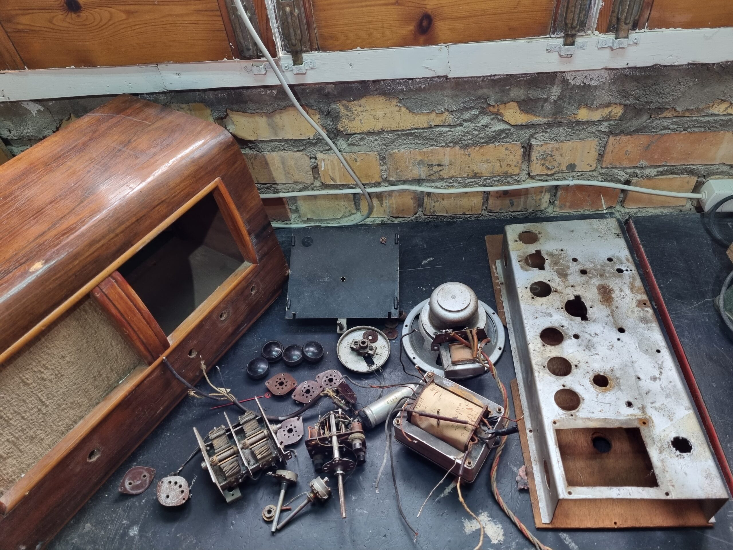
In this first part, we’ll take a look at the radio just as I received it:
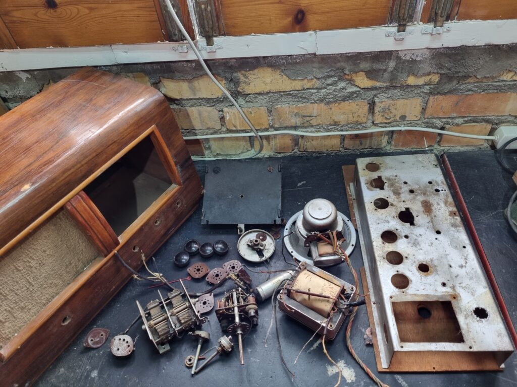
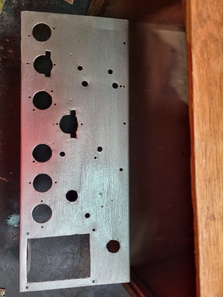
The first thing you notice is that this is a kit-type radio, handmade by someone in France using the standard components that were sold at the time. The chassis clearly looks completely handmade, the power transformer also appears to be artisanal, and without a doubt the radio’s casing is one of the generic types that were commonly sold back then.
You can also see that the person who built this kit did so in what you might call a less-than-professional way. Although you can’t see the underside of the chassis in the photo, the mounting holes still have all the burrs unfiled—an indication that the holes were drilled carelessly without attending to these details. Also, if you zoom into the photo, you’ll notice that several parts, like the voltage selector, are covered in gray paint—undoubtedly because the chassis was painted without bothering to remove or mask the bakelite sockets and connectors, staining them in the process.
If we look closely at the chassis:
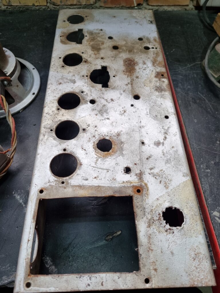
We can see it has seen better days. There are quite a few rusty spots, and as I mentioned, it’s clearly handmade due to the very imperfect holes.
Getting to work, I cleaned the entire chassis inside and out with a sander, taking the opportunity to remove imperfections and burrs from the holes. After leaving the chassis completely clean and rust-free, I applied a gray Hammerite paint to make it look more presentable and, at the same time, protect it from rusting again in the future:
Now it looks much better and will be better protected against rust than it was originally.
If we look at the speaker:
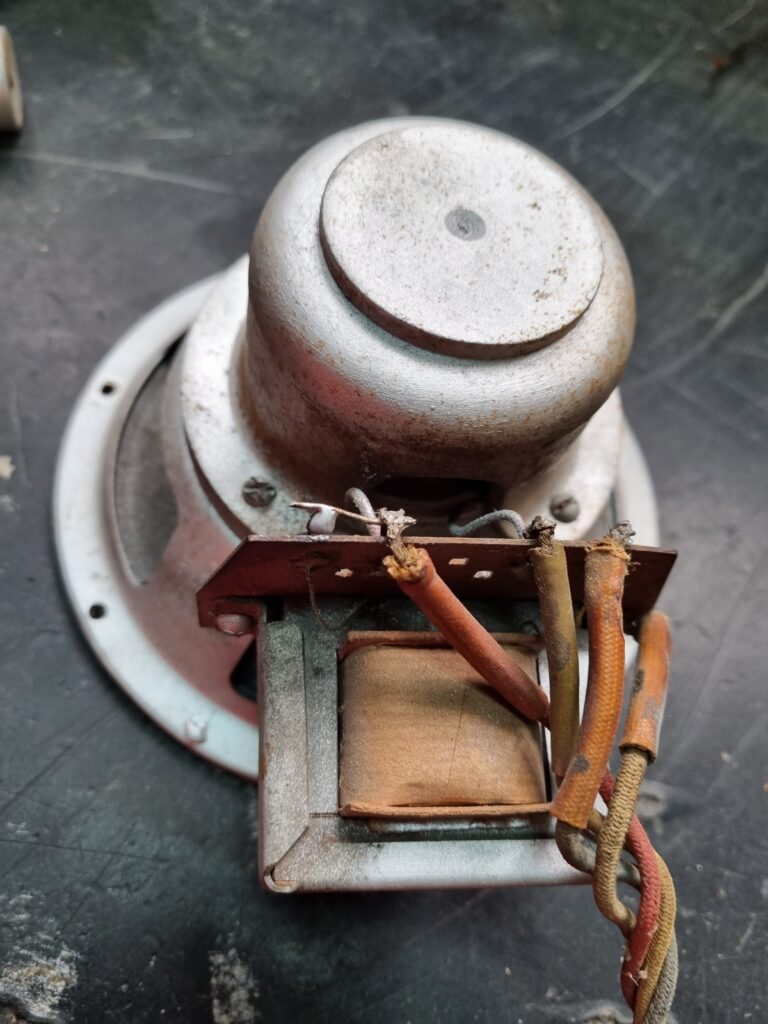
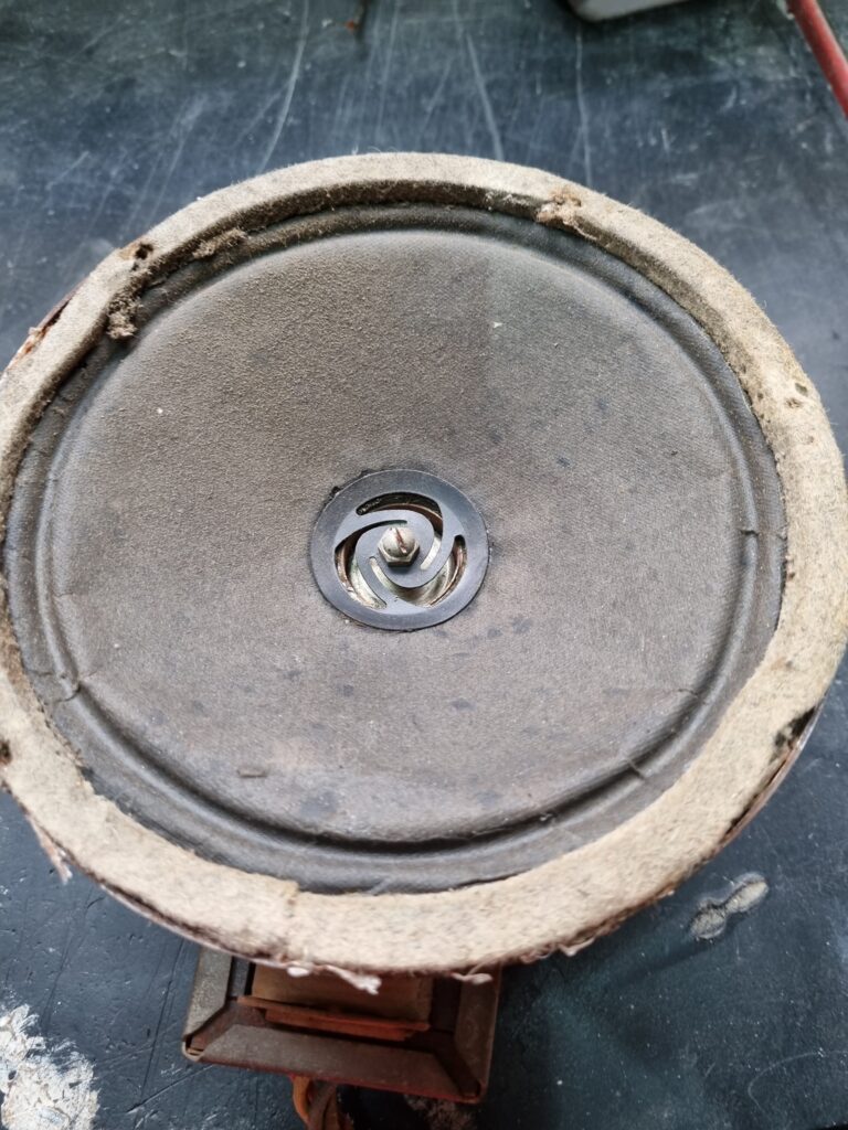
It is a dynamic type speaker, different from modern speakers. In modern speakers, there is a permanent magnet at the back that attracts the cone backwards when at rest. In these old speakers, there is no such magnet because back then they were very large and expensive. Instead, there is an electromagnet, which is simply a copper coil that generates a magnetic field when current passes through it, and that field attracts the cone.
To test this type of speaker, it is important to check if the electromagnet coil (also called the field coil) has continuity. Fortunately, it did, and I also measured its resistance, which was about 2350 Ohms—somewhat high compared to those usually found in other radios.
I also checked that the primary winding of the output transformer had continuity, which it fortunately did. I couldn’t yet verify if the cone worked, although pressing it I didn’t notice any rubbing or strange noises, which is a good sign. The cone itself has some broken parts, which I will repair later.
Looking at the dial glass:
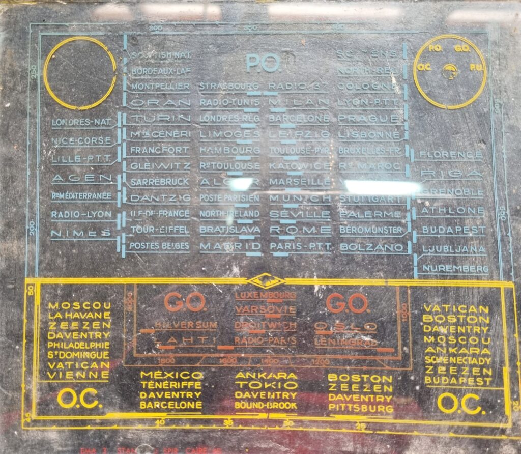
We can see that it still retains its inscriptions. We can also see that the radio has a magic eye and three bands (long wave, medium wave, and short wave), plus a P.U. input (Pick Up, that is, an external audio input intended for a turntable).
As a curiosity, although the dial theoretically shows the P.U. input, the chassis has no connector for the P.U. input—not even a hole to install one—so clearly this function was never usable on this radio. Of course, we will add one in the future.
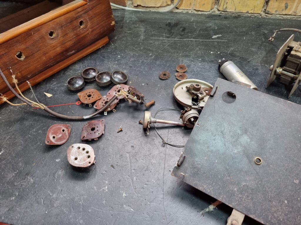
Still, there is a small problem, because although I add that input, there is another one that will be removed…:
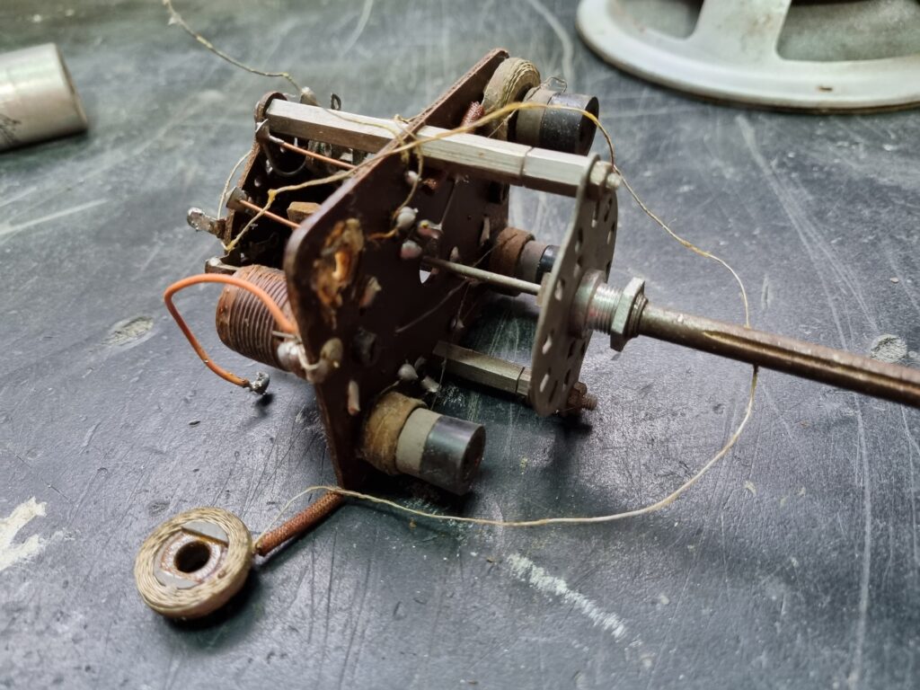
Unfortunately, the band switch is broken. It has that coil exposed and broken, and some other coils have their wires cut. Fortunately, I have antenna and oscillator coils from other radios that cover the same medium wave and short wave frequencies of the radio dial, but I don’t have one that covers long wave, so in the new superheterodyne design I won’t include that band.
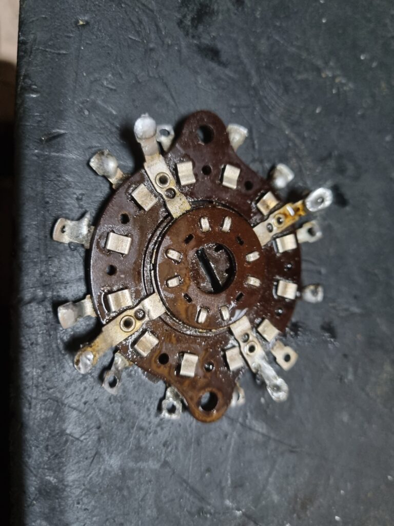
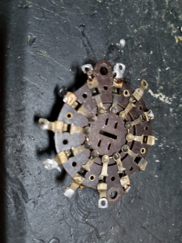
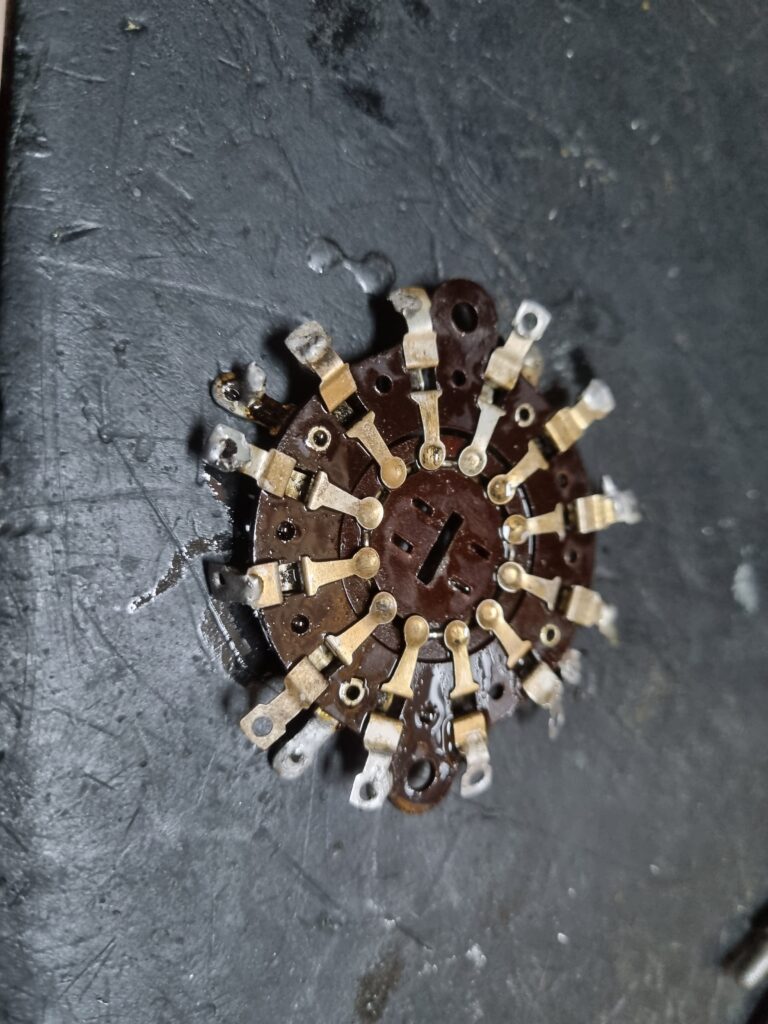
Still, since the switch has 4 positions, I’ll leave the long wave position free to add it in the future if I find antenna and oscillator coils for that band, or if I decide to build them myself. For now, I’m completely disassembling the wave switch:
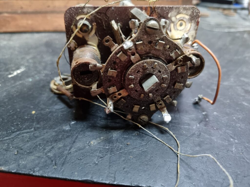
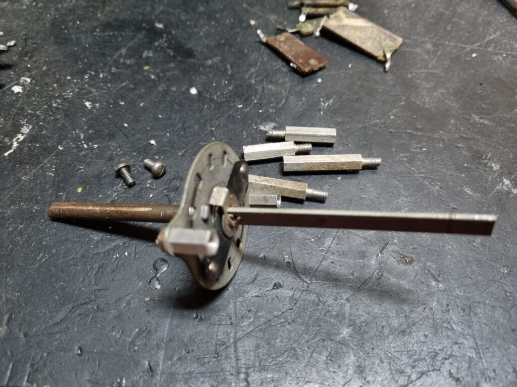
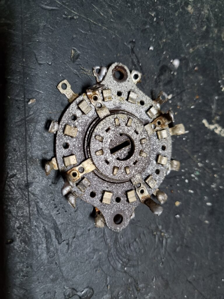
As you can see, the back is covered in paint. However, once disassembled and with a bit of paint thinner, it’s easy to clean up the mess. I also took the opportunity to clean the switch contacts and lubricate the rotation mechanism a bit.
I also use the paint thinner to fix the damage that had been done to the voltage selector.
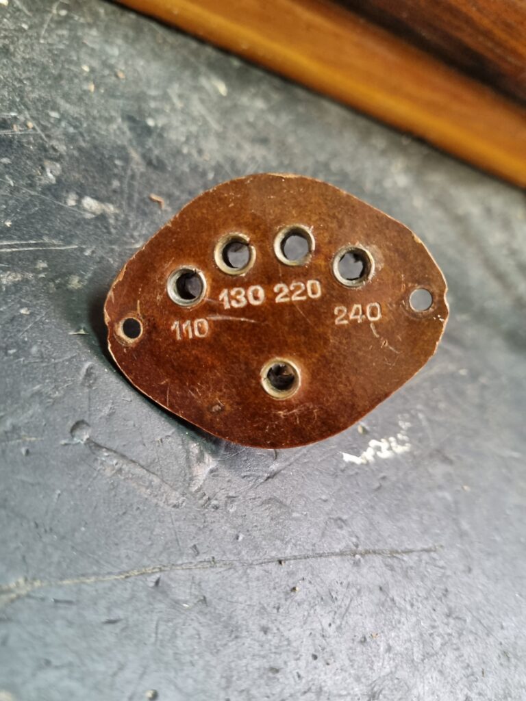
Now it looks like new. As a side note, I will install the voltage selector… but only as decoration. Nowadays, its function doesn’t make much sense since everyone has 230V at home. Besides, it’s a safety hazard to leave it as it is. If it were connected, anyone touching the back could accidentally touch a live terminal and get electrocuted. A design suicide, typical of that era. At least it’s not a universal radio, which would have been much worse.
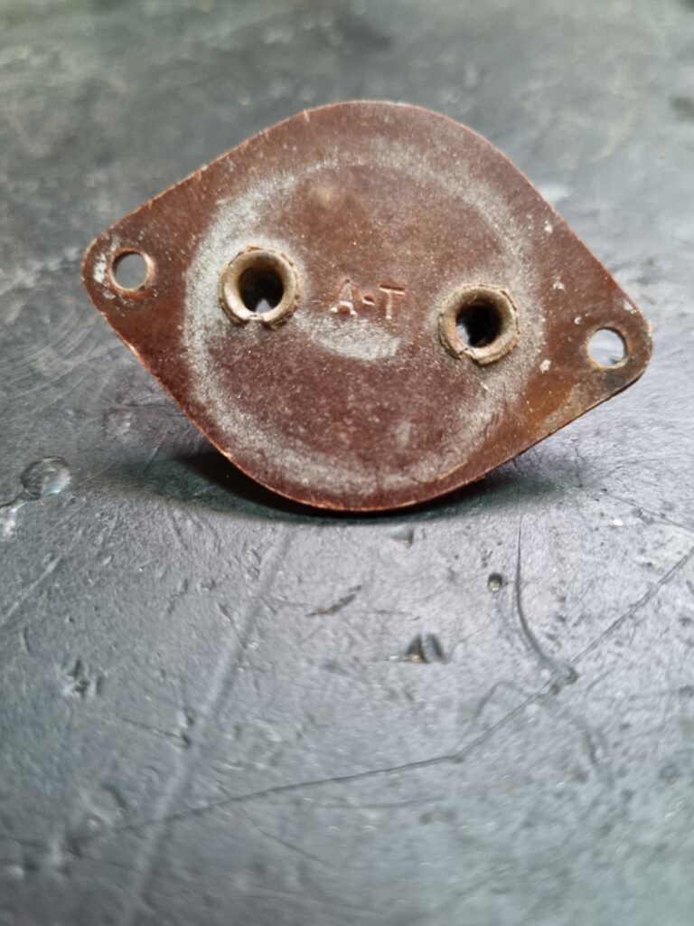
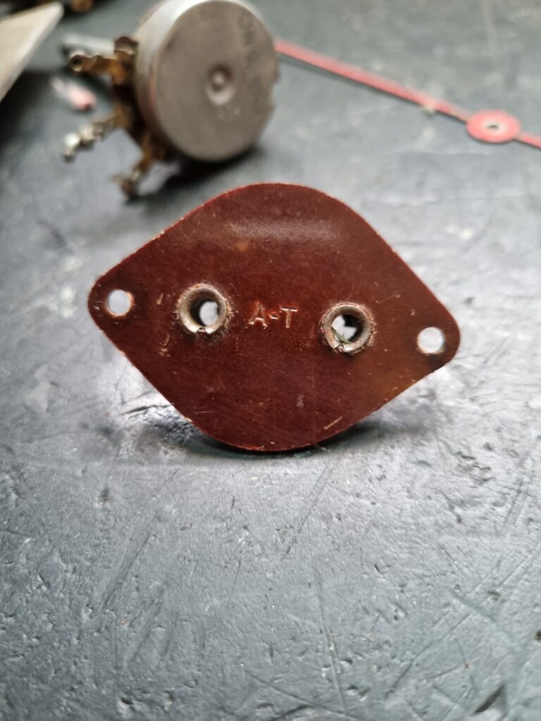
The Antenna-Ground connector was also painted, although less than the voltage selector. Still, the result after cleaning is quite noticeable.
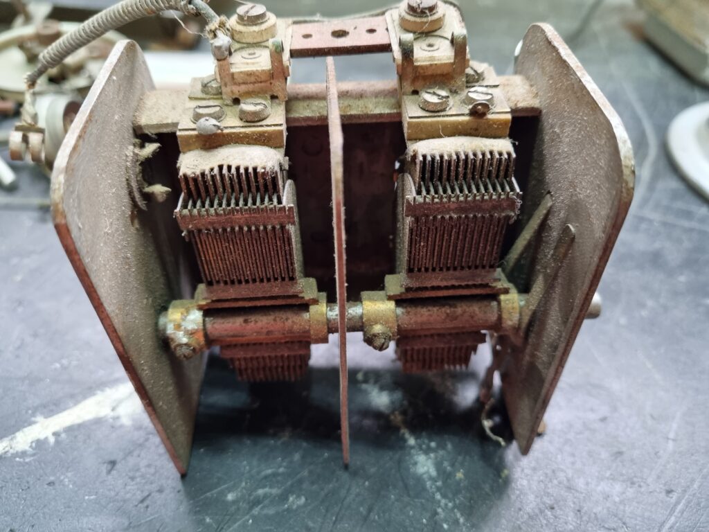
The variable capacitor is a typical two-section type with two tuning trimmers integrated in each section. After a light cleaning and applying some lubricant, it works perfectly.
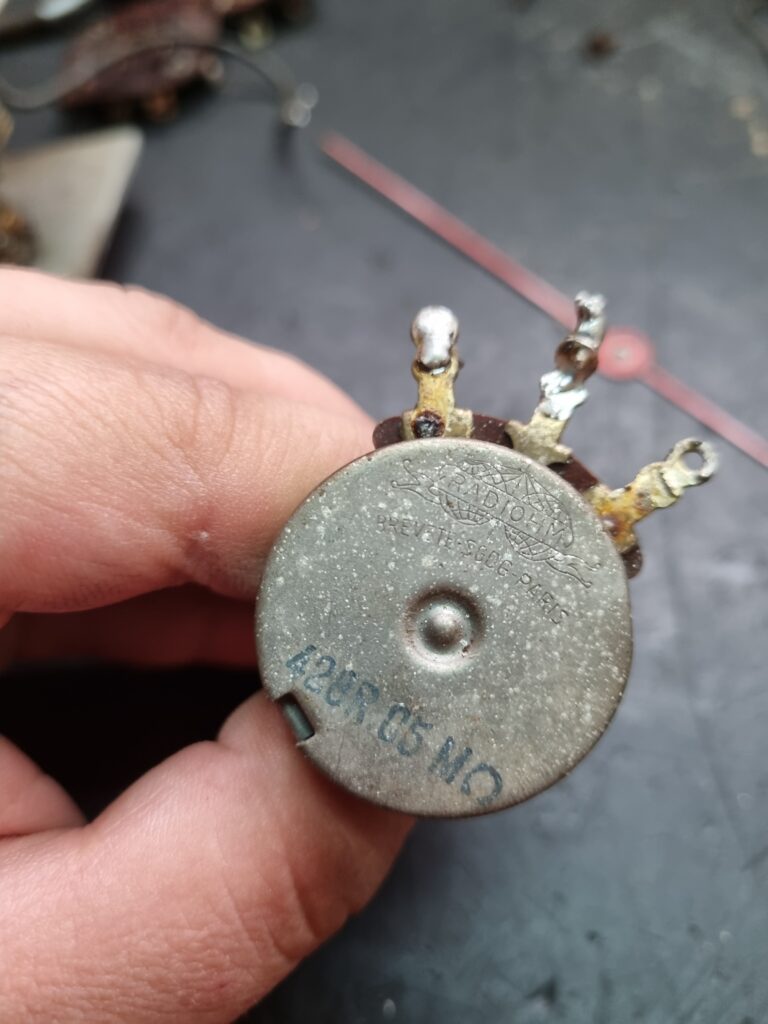
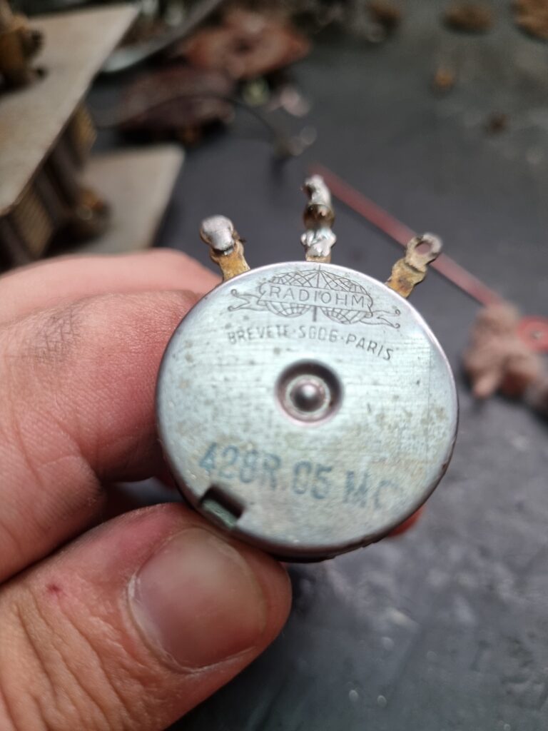
I’ve also cleaned the volume and tone potentiometers, both inside and out. They’re made by Radiohm, which has an interesting logo. Apparently, the company is still operating today.
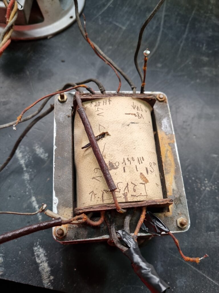
The power transformer clearly looks handmade. The primary and secondary windings aren’t very well labeled, but with a multimeter and some testing with a variac, I identified all the coils.
I taped off the primary taps for other voltages to avoid any issues and left the connection only for 220V for this transformer. One secondary is 6.3V with a center tap?, and the other is 5V with a center tap for the rectifier. The high voltage secondary, although not indicated, is 375-0-375V, which rises to 390-0-390V with today’s 230V supply.
I also measured the resistance of the primary winding and the high voltage secondary. The primary gave me 155 Ohms, and the half of the high voltage secondary about 188 Ohms. Getting these values is important because they’ll be useful later when simulating the behavior of the power supply. I can already say these are quite high values, so the transformer will have poor regulation.
Finally, let’s take a look at the tubes the radio came with:
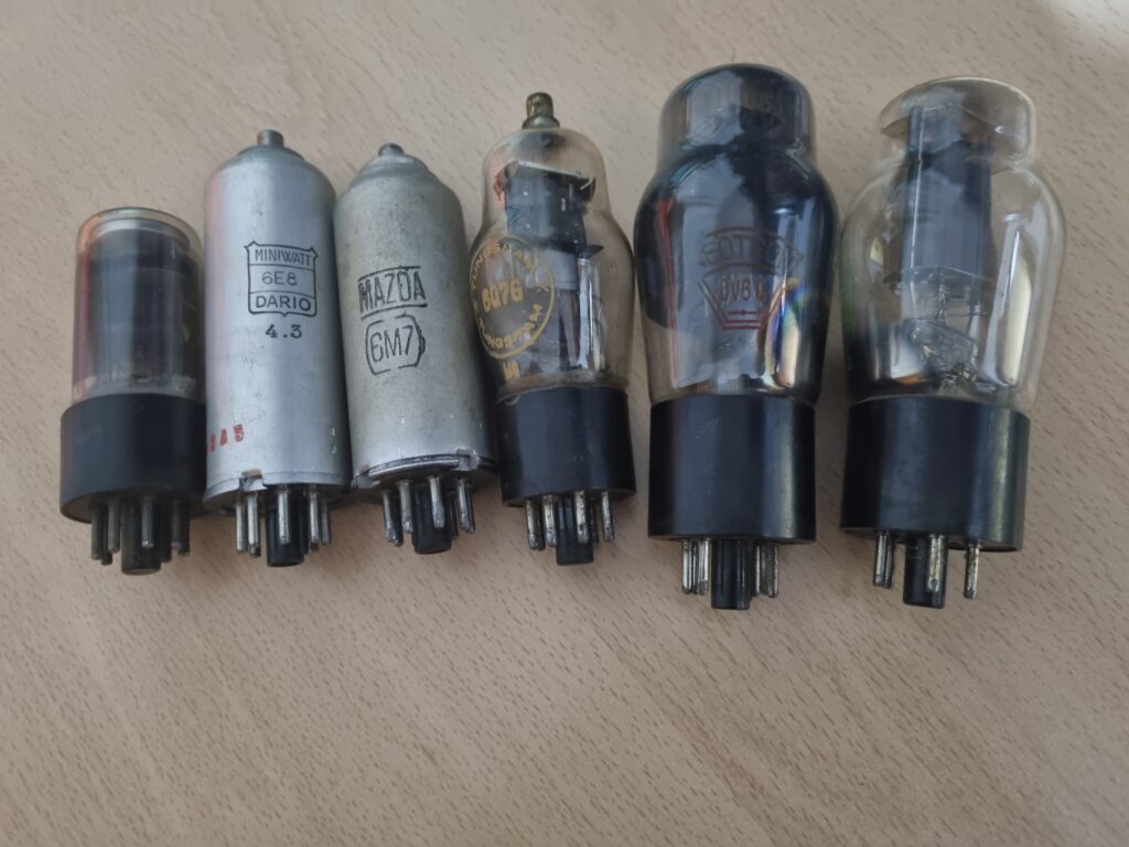
From left to right:
| 6AF7 | Magic eye |
| 6E8 | Mixer-oscillator |
| 6M7 | FI amplifier |
| 6Q7G | Detector and audio preamplifier |
| 6V6G | Audio power amplifier |
| 5Y3GB | High voltage rectifier |
I haven’t checked the condition of the tubes yet with the uTracer, but the first thing I did was check the brightness of the magic eye tube. I had no hope at all, since magic eye tubes are usually worn out due to the use radios get:
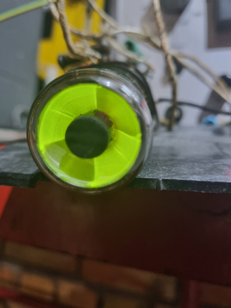
However, to my great surprise, it gives off a more than decent glow; it’s almost like new, which is excellent news. Besides the fact that finding NOS magic eye tubes is getting harder every day, their prices—if you do find them—are through the roof, so this is a relief.
The next part of the series will be the theoretical design of the new superheterodyne. As soon as I have it ready, I will upload it to the blog.