
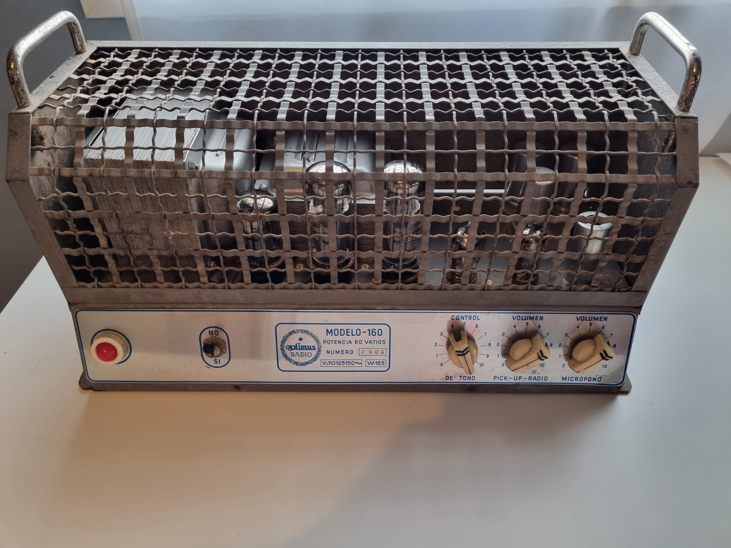
Once again, another Optimus amplifier has fallen into my hands, and this one will be the first I actually own, since unlike other Optimus models, this one was given to me because the original owner didn’t know what to do with it and didn’t want to spend money on restoring it.
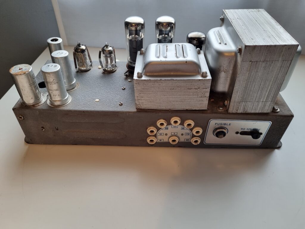
It’s an amplifier from the late 1950s with about 60W power, but designed to be used as a public address (PA) amplifier. One of the issues is that it has high-impedance speaker outputs (40-83-100-125-166-250-500 ohms), so it’s impossible to connect a normal speaker directly; you would need to connect several speakers in series to reach at least 40 ohms.
Another equally serious problem with using this amplifier today is that, aside from the impedance issue, it only works at 110-125-150V and not at 230V. So the power transformer is useless unless you use an autotransformer to step down 230V to one of those three accepted input voltages.
On the other hand, it has two crystal microphone inputs with independent volume controls for each, plus two more inputs for radio and a crystal pick-up, also with their own independent volume controls. Additionally, there’s a tone control, which basically only cuts high frequencies rather than acting as a full tone control.
The downside of these inputs is that they use 5/8″ American Switchcraft-type connectors, which are no longer common nowadays and are quite expensive and hard to find.
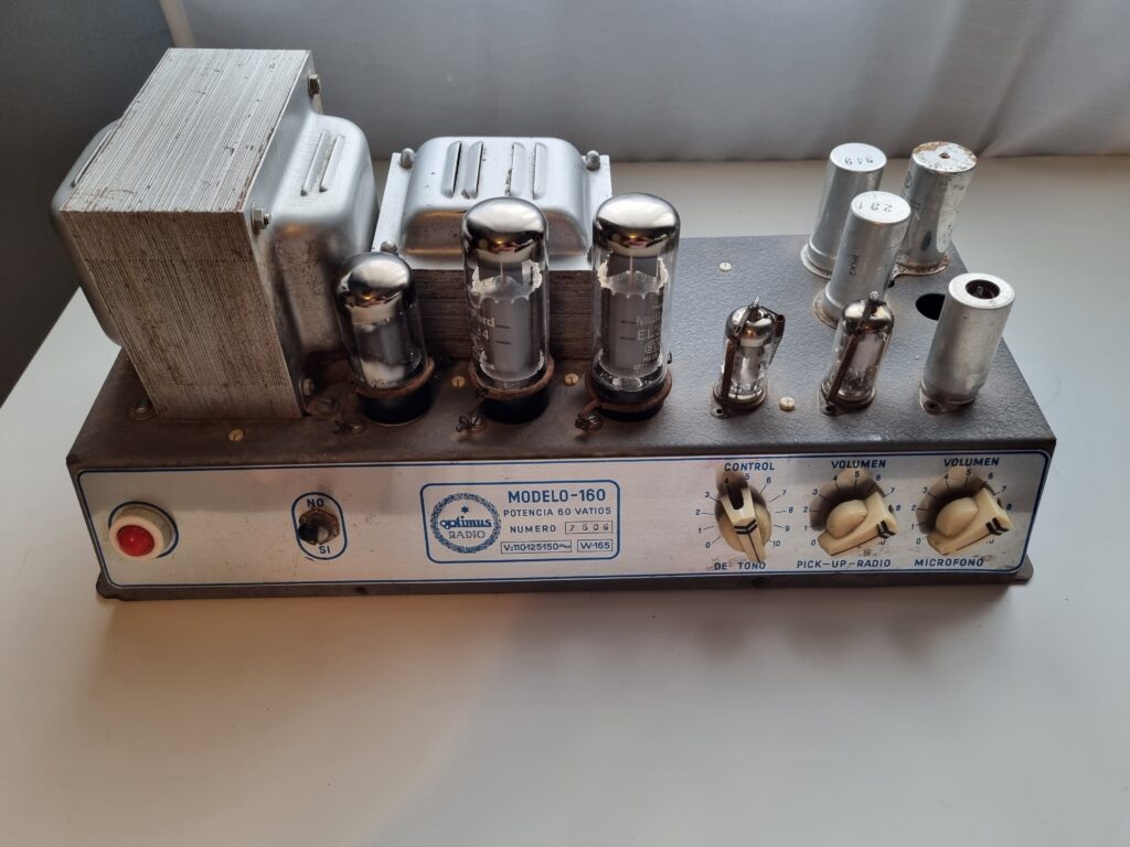
The tubes of the amplifier are:
| GZ34 | High voltage rectifier |
| EL34 | Push pull audio power tube |
| EL34 | Push pull audio power tube |
| ECC83 | Phase Inverter/preamplifier |
| EF86 | Preamplifier |
| EF86 | Microphone preamplifier |
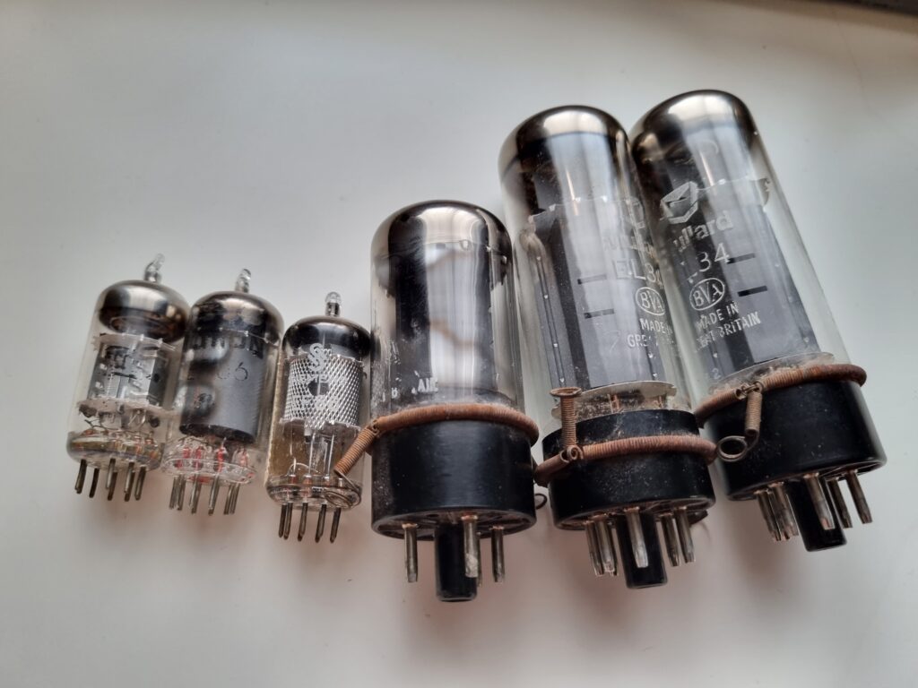
The tubes it comes with are of good quality. The two EL34s are Mullard, manufactured in the second week of April 1972 at the Mullard factory in Blackburn. The GZ34 is also a Mullard, although almost all the letters are faded. The EF86 tubes are one from Siemens and another from Ultron, and as for the ECC83, I’m not exactly sure of the manufacturer since its markings are mostly gone.
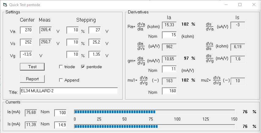
The first thing I do is take a quick look at the condition of the tubes with the uTracer to see if they’re in good shape:
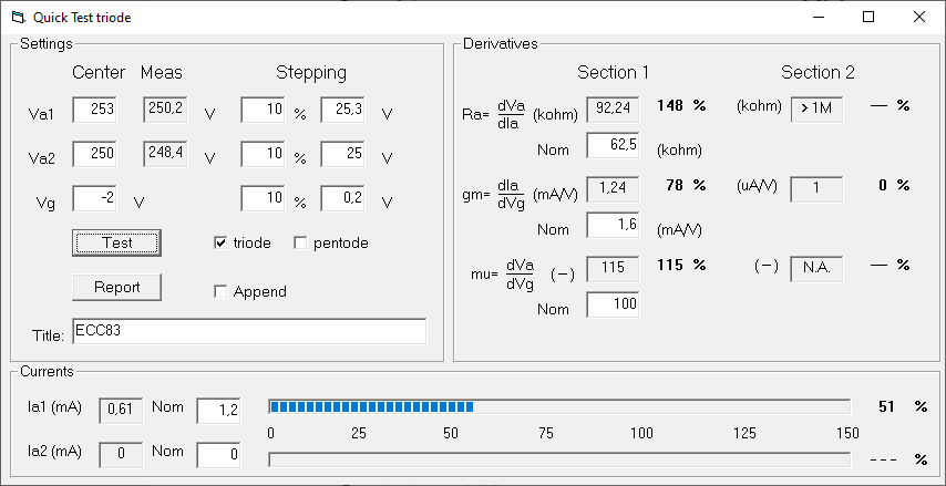
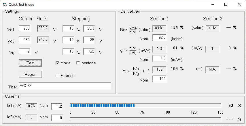
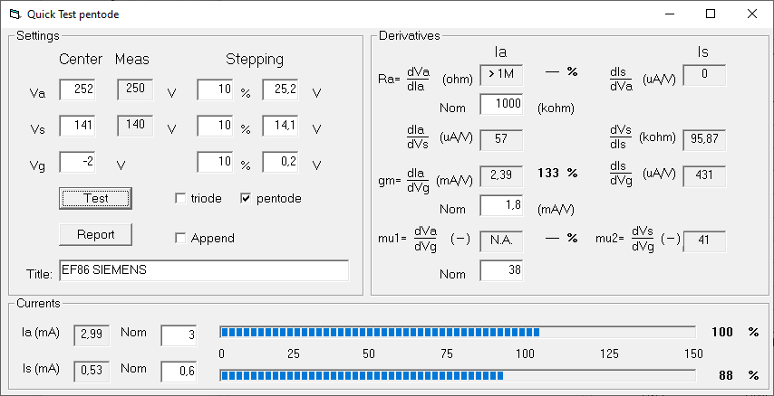
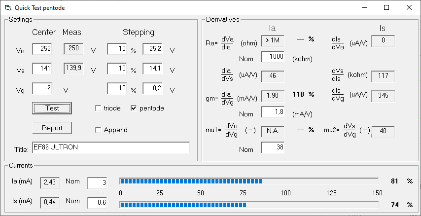
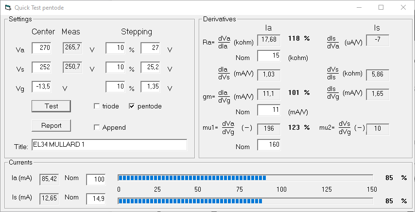
As you can see, the Siemens EF86 is practically new and unused. The Ultron EF86 is a bit more worn but still has very good emission. The two sections of the ECC83, on the other hand, are quite weak, indicating it has seen a lot of use.
Finally, the EL34 tubes are generally somewhat used but still have good emission. The only “issue” is that, as can be seen, they are not matched, since the anode current at the same operating point is not exactly equal, although in reality they are not so far apart as to cause serious operational problems.
After this, let’s take a look inside the circuit:
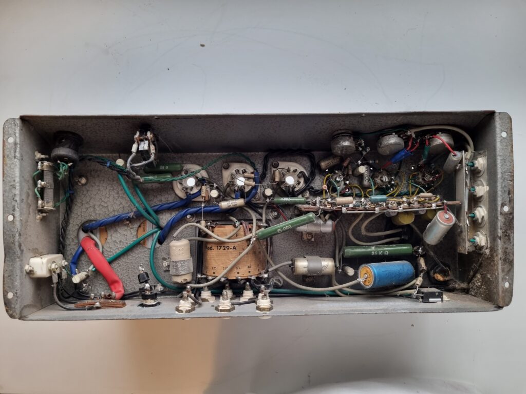
Como sAs you can see, the electrolytic capacitors have leaked and covered the whole area with grime. I also noticed there are capacitors in series without their corresponding balancing resistors in parallel, along with many other small issues…
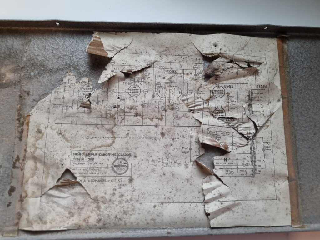
The schematic that came with it is in pretty bad shape, but fortunately, a high-resolution copy can be downloaded from Radiomuseum.
Regarding the circuit’s condition, I found the following issues:
- The wire connecting the circuit to that large blue electrolytic capacitor was completely disconnected.
- In the GZ34 socket, one of the 20-ohm resistors had a cold solder joint from the factory.
- The 25K 30W power resistor was open and showed no resistance.
- All the electrolytic capacitors were damaged.
- Several resistors had drifted significantly from their nominal values.
- Some small resistors were also open.
Clearly, the circuit was not in its best shape. What I didn’t like either was the circuit design itself, because upon reviewing it, several flaws became apparent:
- The EL34 tubes are running way too hard. According to the schematic, they have about 530V on the plates and about 500V on the screens, and they are biased at approximately 55mA each, which causes them to dissipate too much power.
- The ECC83 is not the best tube for phase inversion. Although it works, there are other tubes that perform better in this role, especially at higher frequencies.
- The high voltage filtering is very poor. The capacitors are too small even for that era, and there is no filter choke, so the amplifier likely generates a lot of AC hum.
- Using EF86 tubes at such high gain makes the circuit prone to microphonics, and generally, the amplifier stages have too much gain, worsening the hum problem due to poor filtering.
- The frequency response of the amplifier is very poor. The 3nF capacitor in parallel with the 100K plate resistor of the ECC83 causes almost all frequencies above 1KHz to be barely amplified. This helps “improve” the stability of the negative feedback loop but kills the treble response.
Under these conditions, I have decided to completely disassemble the amplifier and do a radical redesign of the entire circuit. In the next part, I will address the design of the new circuit, which is still in progress.
Meanwhile, if you want to see the latest updates on the amplifier, you can follow them on the blog’s Instagram: https://www.instagram.com/retrocircuitlab